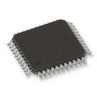
PIC18F45K80-I/PT Microchip Technology, PIC18F45K80-I/PT Datasheet - Page 55

PIC18F45K80-I/PT
Manufacturer Part Number
PIC18F45K80-I/PT
Description
MCU PIC 32KB FLASH 44TQFP
Manufacturer
Microchip Technology
Series
PIC® XLP™ 18Fr
Datasheet
1.PIC18F25K80-ISO.pdf
(628 pages)
Specifications of PIC18F45K80-I/PT
Core Size
8-Bit
Program Memory Size
32KB (16K x 16)
Peripherals
Brown-out Detect/Reset, LVD, POR, PWM, WDT
Core Processor
PIC
Speed
64MHz
Connectivity
ECAN, I²C, LIN, SPI, UART/USART
Number Of I /o
35
Program Memory Type
FLASH
Eeprom Size
1K x 8
Ram Size
3.6K x 8
Voltage - Supply (vcc/vdd)
1.8 V ~ 5.5 V
Data Converters
A/D 11x12b
Oscillator Type
Internal
Operating Temperature
-40°C ~ 85°C
Package / Case
44-TQFP
Controller Family/series
PIC18
Ram Memory Size
4KB
Cpu Speed
16MIPS
No. Of Pwm Channels
5
Embedded Interface Type
I2C, SPI, USART
Processor Series
PIC18F45K80
Core
PIC
Data Bus Width
8 bit
Data Ram Size
1 KB
Interface Type
I2C, SPI, USART
Maximum Clock Frequency
64 MHz
Number Of Programmable I/os
35
Number Of Timers
5
Operating Supply Voltage
1.8 V to 5.5 V
Maximum Operating Temperature
+ 85 C
Mounting Style
SMD/SMT
Lead Free Status / RoHS Status
Lead free / RoHS Compliant
Lead Free Status / RoHS Status
Lead free / RoHS Compliant
Available stocks
Company
Part Number
Manufacturer
Quantity
Price
Company:
Part Number:
PIC18F45K80-I/PT
Manufacturer:
MICROCHIP
Quantity:
1 500
Company:
Part Number:
PIC18F45K80-I/PT
Manufacturer:
PIC
Quantity:
400
Company:
Part Number:
PIC18F45K80-I/PT
Manufacturer:
Microchip Technology
Quantity:
10 000
Part Number:
PIC18F45K80-I/PT
Manufacturer:
MICROCHIP/微芯
Quantity:
20 000
- Current page: 55 of 628
- Download datasheet (6Mb)
3.2
The OSCCON register
aspects of the device clock’s operation. It selects the
oscillator type to be used, which of the power-managed
modes to invoke and the output frequency of the
INTOSC source. It also provides status on the oscillators.
REGISTER 3-1:
2011 Microchip Technology Inc.
bit 7
Legend:
R = Readable bit
-n = Value at POR
bit 7
bit 6-4
bit 3
Note 1:
IDLEN
R/W-0
2:
3:
4:
5:
6:
Control Registers
Reset state depends on the state of the IESO Configuration bit (CONFIG1H<7>).
Modifying these bits will cause an immediate clock frequency switch if the internal oscillator is providing
the device clocks.
Source selected by the INTSRC bit (OSCTUNE<7>).
Modifying these bits will cause an immediate clock source switch.
INTSRC = OSCTUNE<7> and MFIOSEL = OSCCON2<0>.
Lowest power option for an internal source.
IDLEN: Idle Enable bit
1 = Device enters an Idle mode when a SLEEP instruction is executed
0 = Device enters Sleep mode when a SLEEP instruction is executed
IRCF<2:0>: Internal Oscillator Frequency Select bits
111 = HF-INTOSC output frequency is used (16 MHz)
110 = HF-INTOSC/2 output frequency is used (8 MHz, default)
101 = HF-INTOSC/4 output frequency is used (4 MHz)
100 = HF-INTOSC/8 output frequency is used (2 MHz)
011 = HF-INTOSC/16 output frequency is used (1 MHz)
If INTSRC = 0 and MFIOSEL = 0:
010 = HF-INTOSC/32 output frequency is used (500 kHz)
001 = HF-INTOSC/64 output frequency is used (250 kHz)
000 = LF-INTOSC output frequency is used (31.25 kHz)
If INTSRC = 1 and MFIOSEL = 0:
010 = HF-INTOSC/32 output frequency is used (500 kHz)
001 = HF-INTOSC/64 output frequency is used (250 kHz)
000 = HF-INTOSC/512 output frequency is used (31.25 kHz)
If INTSRC = 0 and MFIOSEL = 1:
010 = MF-INTOSC output frequency is used (500 kHz)
001 = MF-INTOSC/2 output frequency is used (250 kHz)
000 = LF-INTOSC output frequency is used (31.25 kHz)
If INTSRC = 1 and MFIOSEL = 1:
010 = MF-INTOSC output frequency is used (500 kHz)
001 = MF-INTOSC/2 output frequency is used (250 kHz)
000 = MF-INTOSC/16 output frequency is used (31.25 kHz)
OSTS: Oscillator Start-up Timer Time-out Status bit
1 = Oscillator Start-up Timer (OST) time-out has expired; primary oscillator is running, as defined by
0 = Oscillator Start-up Timer (OST) time-out is running; primary oscillator is not ready – device is
IRCF2
R/W-1
FOSC<3:0>
running from internal oscillator (HF-INTOSC, MF-INTOSC or LF-INTOSC)
OSCCON: OSCILLATOR CONTROL REGISTER
(Register
(2)
W = Writable bit
‘1’ = Bit is set
IRCF1
3-1) controls the main
R/W-0
(2)
IRCF0
R/W-0
(3,5)
(3,5)
(3,5)
(3,5)
Preliminary
(2)
U = Unimplemented bit, read as ‘0’
‘0’ = Bit is cleared
PIC18F66K80 FAMILY
OSTS
The OSCTUNE register
tuning and operation of the internal oscillator block. It also
implements the PLLEN bit which controls the operation of
the Phase Locked Loop (PLL) (see
Frequency
R
(1)
(1)
(2)
(6)
(6)
Multiplier”).
HFIOFS
R-0
x = Bit is unknown
(Register
SCS1
R/W-0
(4)
Section 3.5.3 “PLL
3-3) controls the
DS39977C-page 55
SCS0
R/W-0
(4)
bit 0
Related parts for PIC18F45K80-I/PT
Image
Part Number
Description
Manufacturer
Datasheet
Request
R

Part Number:
Description:
Manufacturer:
Microchip Technology Inc.
Datasheet:

Part Number:
Description:
Manufacturer:
Microchip Technology Inc.
Datasheet:

Part Number:
Description:
Manufacturer:
Microchip Technology Inc.
Datasheet:

Part Number:
Description:
Manufacturer:
Microchip Technology Inc.
Datasheet:

Part Number:
Description:
Manufacturer:
Microchip Technology Inc.
Datasheet:

Part Number:
Description:
Manufacturer:
Microchip Technology Inc.
Datasheet:

Part Number:
Description:
Manufacturer:
Microchip Technology Inc.
Datasheet:

Part Number:
Description:
Manufacturer:
Microchip Technology Inc.
Datasheet:


