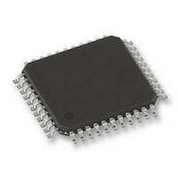
PIC18F45K80-I/PT Microchip Technology, PIC18F45K80-I/PT Datasheet - Page 614

PIC18F45K80-I/PT
Manufacturer Part Number
PIC18F45K80-I/PT
Description
MCU PIC 32KB FLASH 44TQFP
Manufacturer
Microchip Technology
Series
PIC® XLP™ 18Fr
Datasheet
1.PIC18F25K80-ISO.pdf
(628 pages)
Specifications of PIC18F45K80-I/PT
Core Size
8-Bit
Program Memory Size
32KB (16K x 16)
Peripherals
Brown-out Detect/Reset, LVD, POR, PWM, WDT
Core Processor
PIC
Speed
64MHz
Connectivity
ECAN, I²C, LIN, SPI, UART/USART
Number Of I /o
35
Program Memory Type
FLASH
Eeprom Size
1K x 8
Ram Size
3.6K x 8
Voltage - Supply (vcc/vdd)
1.8 V ~ 5.5 V
Data Converters
A/D 11x12b
Oscillator Type
Internal
Operating Temperature
-40°C ~ 85°C
Package / Case
44-TQFP
Controller Family/series
PIC18
Ram Memory Size
4KB
Cpu Speed
16MIPS
No. Of Pwm Channels
5
Embedded Interface Type
I2C, SPI, USART
Processor Series
PIC18F45K80
Core
PIC
Data Bus Width
8 bit
Data Ram Size
1 KB
Interface Type
I2C, SPI, USART
Maximum Clock Frequency
64 MHz
Number Of Programmable I/os
35
Number Of Timers
5
Operating Supply Voltage
1.8 V to 5.5 V
Maximum Operating Temperature
+ 85 C
Mounting Style
SMD/SMT
Lead Free Status / RoHS Status
Lead free / RoHS Compliant
Lead Free Status / RoHS Status
Lead free / RoHS Compliant
Available stocks
Company
Part Number
Manufacturer
Quantity
Price
Company:
Part Number:
PIC18F45K80-I/PT
Manufacturer:
MICROCHIP
Quantity:
1 500
Company:
Part Number:
PIC18F45K80-I/PT
Manufacturer:
PIC
Quantity:
400
Company:
Part Number:
PIC18F45K80-I/PT
Manufacturer:
Microchip Technology
Quantity:
10 000
Part Number:
PIC18F45K80-I/PT
Manufacturer:
MICROCHIP/微芯
Quantity:
20 000
- Current page: 614 of 628
- Download datasheet (6Mb)
PIC18F66K80 FAMILY
Effect on Standard PIC18 Instructions .............................. 534
Effects of Power-Managed Modes on Various
Electrical Characteristics................................................... 541
Enhanced Capture/Compare/PWM (ECCP) ..................... 271
DS39977C-page 614
Error Detection .......................................................... 456
Error Modes State (diagram) .................................... 457
Error Recognition Mode ............................................ 443
Filter-Mask Truth (table)............................................ 448
Functional Modes...................................................... 443
Information Processing Time (IPT) ........................... 453
Lengthening a Bit Period........................................... 454
Listen Only Mode ...................................................... 443
Loopback Mode ........................................................ 443
Message Acceptance Filters and Masks .......... 425, 448
Message Acceptance Mask and Filter
Message Reception .................................................. 447
Normal Mode ............................................................ 442
Oscillator Tolerance .................................................. 455
Overview ................................................................... 395
Phase Buffer Segments ............................................ 453
Programmable TX/RX and Auto-RTR Buffers .......... 417
Programming Time Segments .................................. 455
Propagation Segment ............................................... 453
Sample Point............................................................. 453
Shortening a Bit Period ............................................. 455
Synchronization ........................................................ 454
Synchronization Segment ......................................... 453
Time Quanta ............................................................. 453
Values for ICODE (table) .......................................... 458
Clock Sources............................................................. 65
Capture Mode. See Capture.
Compare Mode. See Compare.
ECCP Mode and Timer Resources........................... 274
Enhanced PWM Mode .............................................. 277
Acknowledge..................................................... 456
Bit...................................................................... 456
CRC .................................................................. 456
Error Modes and Counters................................ 456
Error States....................................................... 456
Form.................................................................. 456
Stuff Bit ............................................................. 456
Mode 0 (Legacy Mode) ..................................... 443
Mode 1 (Enhanced Legacy Mode).................... 443
Mode 2 (Enhanced FIFO Mode) ....................... 444
Operation .......................................................... 449
Enhanced FIFO Mode....................................... 448
Priority............................................................... 447
Time-Stamping.................................................. 448
Hard .................................................................. 454
Resynchronization ............................................ 454
Rules................................................................. 454
Auto-Restart...................................................... 286
Auto-Shutdown ................................................. 284
Direction Change in Full-Bridge
Full-Bridge Application ...................................... 281
Full-Bridge Mode............................................... 281
Half-Bridge Application ..................................... 280
Half-Bridge Application Examples..................... 287
Half-Bridge Mode .............................................. 280
Output Relationships (Active-High and
Output Relationships Diagram .......................... 279
Programmable Dead-Band Delay ..................... 287
Output Mode ............................................. 283
Active-Low) ............................................... 278
Preliminary
Enhanced Capture/Compare/PWM (ECCP) and
Enhanced Universal Synchronous Asynchronous
Equations
Errata .................................................................................. 11
Error Recognition Mode.................................................... 442
EUSART
Extended Instruction Set
External Oscillator Modes
Outputs and Configuration........................................ 274
Timer1/2/3/4 Associated Registers........................... 292
Receiver Transmitter (EUSART). See EUSART.
16 x 16 Signed Multiplication Algorithm.................... 152
16 x 16 Unsigned Multiplication Algorithm................ 152
A/D Acquisition Time ................................................ 372
A/D Minimum Charging Time.................................... 372
Calculating the Minimum Required
Asynchronous Mode ................................................. 349
Baud Rate Generator
Baud Rate Generator (BRG) .................................... 343
Synchronous Master Mode....................................... 357
Synchronous Slave Mode......................................... 361
ADDFSR ................................................................... 530
ADDULNK................................................................. 530
CALLW ..................................................................... 531
MOVSF ..................................................................... 531
MOVSS..................................................................... 532
PUSHL...................................................................... 532
SUBFSR ................................................................... 533
SUBULNK................................................................. 533
Clock Input (EC Modes).............................................. 61
HS............................................................................... 60
Shoot-Through Current..................................... 287
Start-up Considerations.................................... 284
Acquisition Time ............................................... 372
12-Bit Break Transmit and Receive.................. 356
Associated Registers, Receive......................... 353
Associated Registers, Transmit........................ 351
Auto-Wake-up on Sync Break .......................... 354
Receiver ........................................................... 352
Setting up 9-Bit Mode with
Transmitter ....................................................... 349
Operation in Power-Managed Mode................. 343
Associated Registers........................................ 344
Auto-Baud Rate Detect..................................... 347
Baud Rate Error, Calculating............................ 344
Baud Rates, Asynchronous Modes .................. 345
High Baud Rate Select (BRGH Bit) .................. 343
Sampling........................................................... 343
Associated Registers, Receive......................... 360
Associated Registers, Transmit........................ 358
Reception ......................................................... 359
Transmission .................................................... 357
Associated Registers, Receive......................... 362
Associated Registers, Transmit........................ 361
Reception ......................................................... 362
Transmission .................................................... 361
Address Detect ......................................... 352
2011 Microchip Technology Inc.
Related parts for PIC18F45K80-I/PT
Image
Part Number
Description
Manufacturer
Datasheet
Request
R

Part Number:
Description:
Manufacturer:
Microchip Technology Inc.
Datasheet:

Part Number:
Description:
Manufacturer:
Microchip Technology Inc.
Datasheet:

Part Number:
Description:
Manufacturer:
Microchip Technology Inc.
Datasheet:

Part Number:
Description:
Manufacturer:
Microchip Technology Inc.
Datasheet:

Part Number:
Description:
Manufacturer:
Microchip Technology Inc.
Datasheet:

Part Number:
Description:
Manufacturer:
Microchip Technology Inc.
Datasheet:

Part Number:
Description:
Manufacturer:
Microchip Technology Inc.
Datasheet:

Part Number:
Description:
Manufacturer:
Microchip Technology Inc.
Datasheet:


