PIC18F45K80-I/PT Microchip Technology, PIC18F45K80-I/PT Datasheet - Page 74
PIC18F45K80-I/PT
Manufacturer Part Number
PIC18F45K80-I/PT
Description
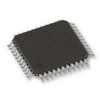
MCU PIC 32KB FLASH 44TQFP
Manufacturer
Microchip Technology
Series
PIC® XLP™ 18Fr
Datasheet
1.PIC18F25K80-ISO.pdf
(628 pages)
Specifications of PIC18F45K80-I/PT
Core Size
8-Bit
Program Memory Size
32KB (16K x 16)
Peripherals
Brown-out Detect/Reset, LVD, POR, PWM, WDT
Core Processor
PIC
Speed
64MHz
Connectivity
ECAN, I²C, LIN, SPI, UART/USART
Number Of I /o
35
Program Memory Type
FLASH
Eeprom Size
1K x 8
Ram Size
3.6K x 8
Voltage - Supply (vcc/vdd)
1.8 V ~ 5.5 V
Data Converters
A/D 11x12b
Oscillator Type
Internal
Operating Temperature
-40°C ~ 85°C
Package / Case
44-TQFP
Controller Family/series
PIC18
Ram Memory Size
4KB
Cpu Speed
16MIPS
No. Of Pwm Channels
5
Embedded Interface Type
I2C, SPI, USART
Processor Series
PIC18F45K80
Core
PIC
Data Bus Width
8 bit
Data Ram Size
1 KB
Interface Type
I2C, SPI, USART
Maximum Clock Frequency
64 MHz
Number Of Programmable I/os
35
Number Of Timers
5
Operating Supply Voltage
1.8 V to 5.5 V
Maximum Operating Temperature
+ 85 C
Mounting Style
SMD/SMT
Lead Free Status / RoHS Status
Lead free / RoHS Compliant
Lead Free Status / RoHS Status
Lead free / RoHS Compliant
Available stocks
Company
Part Number
Manufacturer
Quantity
Price
Company:

Part Number:
PIC18F45K80-I/PT
Manufacturer:
MICROCHIP
Quantity:
1 500
Company:
Part Number:
PIC18F45K80-I/PT
Manufacturer:
PIC
Quantity:
400
Company:
Part Number:
PIC18F45K80-I/PT
Manufacturer:
Microchip Technology
Quantity:
10 000
Part Number:
PIC18F45K80-I/PT
Manufacturer:
MICROCHIP/微芯
Quantity:
20 000


PIC18F66K80 FAMILY
4.4.3
In RC_IDLE mode, the CPU is disabled but the periph-
erals continue to be clocked from the internal oscillator
block using the INTOSC multiplexer. This mode
provides controllable power conservation during Idle
periods.
From RC_RUN, this mode is entered by setting the
IDLEN bit and executing a SLEEP instruction. If the
device is in another Run mode, first set IDLEN, then set
the SCS1 bit and execute SLEEP. To maintain software
compatibility with future devices, it is recommended
that SCS0 also be cleared, though its value is ignored.
The INTOSC multiplexer may be used to select a
higher clock frequency by modifying the IRCF bits
before executing the SLEEP instruction. When the
clock source is switched to the INTOSC multiplexer, the
primary oscillator is shut down and the OSTS bit is
cleared.
If the IRCF bits are set to any non-zero value, or the
INTSRC/MFIOSEL bit is set, the INTOSC output is
enabled. The HFIOFS/MFIOFS bits become set, after
the INTOSC output becomes stable, after an interval of
T
the HFIOFS/MFIOFS bits, see
Clocks to the peripherals continue while the INTOSC
source stabilizes. The HFIOFS/MFIOFS bits will
remain set if the IRCF bits were previously at a non-
zero value or if INTSRC was set before the SLEEP
instruction was executed and the INTOSC source was
already stable. If the IRCF bits and INTSRC are all
clear, the INTOSC output will not be enabled, the
HFIOFS/MFIOFS bits will remain clear and there will be
no indication of the current clock source.
When a wake event occurs, the peripherals continue to
be clocked from the INTOSC multiplexer. After a delay
of T
event, the CPU begins executing code clocked by the
INTOSC multiplexer. The IDLEN and SCS bits are not
affected by the wake-up. The INTOSC source will
continue to run if either the WDT or the Fail-Safe Clock
Monitor is enabled.
DS39977C-page 74
IOBST
CSD
(Parameter 38,
(Parameter 38,
RC_IDLE MODE
Table
Table
31-11). For information on
31-11) following the wake
Table
4-3.
Preliminary
4.5
Idle mode allows users to substantially reduce power
consumption by stopping the CPU clock. Even so,
peripheral modules still remain clocked, and thus, con-
sume power. There may be cases where the application
needs what this mode does not provide: the allocation of
power resources to the CPU processing with minimal
power consumption from the peripherals.
PIC18F66K80 family devices address this requirement
by allowing peripheral modules to be selectively
disabled,
consumption. This can be done with two control bits:
• Peripheral Enable bit, generically named XXXEN –
• Peripheral Module Disable (PMD) bit, generically
Disabling a module by clearing its XXXEN bit disables
the module’s functionality, but leaves its registers
available to be read and written to. This reduces power
consumption, but not by as much as the second
approach.
Most peripheral modules have an enable bit.
In contrast, setting the PMD bit for a module disables
all clock sources to that module, reducing its power
consumption to an absolute minimum. In this state, the
control and status registers associated with the periph-
eral are also disabled, so writes to those registers have
no effect and read values are invalid. Many peripheral
modules have a corresponding PMD bit.
There are three PMD registers in PIC18F66K80 family
devices: PMD0, PMD1 and PMD2. These registers
have bits associated with each module for disabling or
enabling a particular peripheral.
Located in the respective module’s main control
register
named, XXXMD – Located in one of the PMDx
Control registers (PMD0, PMD1 or PMD2)
Selective Peripheral Module
Control
reducing
or
2011 Microchip Technology Inc.
eliminating
their
power
Related parts for PIC18F45K80-I/PT
Image
Part Number
Description
Manufacturer
Datasheet
Request
R

Part Number:
Description:
Manufacturer:
Microchip Technology Inc.
Datasheet:
Part Number:
Description:
Manufacturer:
Microchip Technology Inc.
Datasheet:
Part Number:
Description:
Manufacturer:
Microchip Technology Inc.
Datasheet:
Part Number:
Description:
Manufacturer:
Microchip Technology Inc.
Datasheet:
Part Number:
Description:
Manufacturer:
Microchip Technology Inc.
Datasheet:
Part Number:
Description:
Manufacturer:
Microchip Technology Inc.
Datasheet:
Part Number:
Description:
Manufacturer:
Microchip Technology Inc.
Datasheet:
Part Number:
Description:
Manufacturer:
Microchip Technology Inc.
Datasheet: