AD532SD Analog Devices Inc, AD532SD Datasheet - Page 5
AD532SD
Manufacturer Part Number
AD532SD
Description
Multiplexer IC
Manufacturer
Analog Devices Inc
Specifications of AD532SD
Ic Function
Analog Multiplier/Divider IC
Package/case
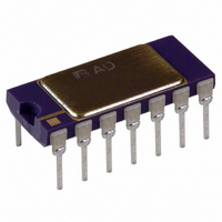
14-CDIP
Accuracy
1 %
Leaded Process Compatible
No
Number Of Channels
4
Output Voltage
13V
Peak Reflow Compatible (260 C)
No
Supply Voltage Max
18V
Rohs Status
RoHS non-compliant
Function
Analog Multiplier/Divider
Number Of Bits/stages
4-Quadrant
Package / Case
14-CDIP (0.300", 7.62mm)
Lead Free Status / RoHS Status
Contains lead / RoHS non-compliant
Available stocks
Company
Part Number
Manufacturer
Quantity
Price

Company:
Part Number:
AD532SD/883B
Manufacturer:
ADI
Quantity:
676


DYNAMIC CHARACTERISTICS
The closed loop frequency response of the AD532 in the multi-
plier mode typically exhibits a 3 dB bandwidth of 1 MHz and
rolls off at 6 dB/octave thereafter. Response through all inputs is
essentially the same as shown in Figure 7. In the divide mode,
the closed loop frequency response is a function of the absolute
value of the denominator voltage as shown in Figure 8.
Stable operation is maintained with capacitive loads to 1000 pF
in all modes, except the square root for which 50 pF is a safe
upper limit. Higher capacitive loads can be driven if a 100
resistor is connected in series with the output for isolation.
POWER SUPPLY CONSIDERATIONS
Although the AD532 is tested and specified with 15 V dc
supplies, it may be operated at any supply voltage from 10 V
to 18 V for the J and K versions, and 10 V to 22 V for the S
version. The input and output signals must be reduced propor-
tionately to prevent saturation; however, with supply voltages
below 15 V, as shown in Figure 9. Since power supply sensitiv-
ity is not dependent on external null networks as in the AD530
and other conventionally nulled multipliers, the power supply
rejection ratios are improved from 3 to 40 times in the AD532.
REV. B
Figure 8. Frequency Response, Dividing
Figure 9. Signal Swing vs. Supply
–5–
NOISE CHARACTERISTICS
All AD532s are screened on a sampling basis to assure that
output noise will have no appreciable effect on accuracy. Typi-
cal spot noise vs. frequency is shown in Figure 10.
APPLICATIONS CONSIDERATIONS
The performance and ease of use of the AD532 is achieved
through the laser trimming of thin-film resistors deposited di-
rectly on the monolithic chip. This trimming-on-the-chip tech-
nique provides a number of significant advantages in terms of
cost, reliability and flexibility over conventional in-package
trimming of off-the-chip resistors mounted or deposited on a
hybrid substrate.
First and foremost, trimming on the chip eliminates the need
for a hybrid substrate and the additional bonding wires that are
required between the resistors and the multiplier chip. By trim-
ming more appropriate resistors on the AD532 chip itself, the
second input terminals that were once committed to external
trimming networks (e.g., AD530) have been freed to allow fully
differential operation at both the X and Y inputs. Further, the
requirement for an input attenuator to adjust the gain at the Y
input has been eliminated, letting the user take full advantage of
the high input impedance properties of the input differential
amplifiers. Thus, the AD532 offers greater flexibility for both
algebraic computation and transducer instrumentation
applications.
Finally, provision for fine trimming the output voltage offset has
been included. This connection is optional, however, as the
AD532 has been factory-trimmed for total performance as
described in the listed specifications.
REPLACING OTHER IC MULTIPLIERS
Existing designs using IC multipliers that require external trim-
ming networks (such as the AD530) can be simplified using the
pin-for-pin replaceability of the AD532 by merely grounding
the X
be grounded when unused.)
2
, Y
2
and V
Figure 10. Spot Noise vs. Frequency
OS
terminals. (The V
OS
terminal should always
AD532
Related parts for AD532SD
Image
Part Number
Description
Manufacturer
Datasheet
Request
R

Part Number:
Description:
±1.7g Dual-Axis IMEMS Accelerometer Evaluation Board
Manufacturer:
Analog Devices Inc
Datasheet:

Part Number:
Description:
Inertial Sensor Evaluation System
Manufacturer:
Analog Devices Inc
Datasheet:
Part Number:
Description:
Manufacturer:
Analog Devices Inc
Datasheet:
Part Number:
Description:
Manufacturer:
Analog Devices Inc
Datasheet:
Part Number:
Description:
Manufacturer:
Analog Devices Inc
Datasheet:
Part Number:
Description:
Manufacturer:
Analog Devices Inc
Datasheet:
Part Number:
Description:
Manufacturer:
Analog Devices Inc
Datasheet:
Part Number:
Description:
Manufacturer:
Analog Devices Inc
Datasheet:
Part Number:
Description:
Manufacturer:
Analog Devices Inc
Datasheet:
Part Number:
Description:
Manufacturer:
Analog Devices Inc
Datasheet:
Part Number:
Description:
Manufacturer:
Analog Devices Inc
Datasheet:
Part Number:
Description:
Manufacturer:
Analog Devices Inc
Datasheet:
Part Number:
Description:
Manufacturer:
Analog Devices Inc
Datasheet: