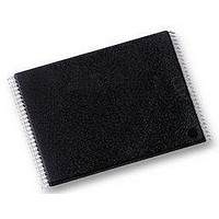
S29AL004D70TFI010 Spansion Inc., S29AL004D70TFI010 Datasheet - Page 21

S29AL004D70TFI010
Manufacturer Part Number
S29AL004D70TFI010
Description
Flash Memory IC
Manufacturer
Spansion Inc.
Datasheet
1.S29AL004D70TAI020.pdf
(55 pages)
Specifications of S29AL004D70TFI010
Memory Size
4Mbit
Memory Configuration
512K X 8 / 256K X 16
Ic Interface Type
Parallel
Access Time
70ns
Memory Case Style
TSOP
No. Of Pins
48
Operating Temperature Range
-40°C To +85°C
Lead Free Status / RoHS Status
Lead free / RoHS Compliant
Available stocks
Company
Part Number
Manufacturer
Quantity
Price
Company:
Part Number:
S29AL004D70TFI010
Manufacturer:
SPANSION
Quantity:
5 530
Company:
Part Number:
S29AL004D70TFI010
Manufacturer:
SPANSION
Quantity:
1 690
Company:
Part Number:
S29AL004D70TFI010
Manufacturer:
SPANSION
Quantity:
6 250
Company:
Part Number:
S29AL004D70TFI010H
Manufacturer:
SPANSION
Quantity:
50
February 18, 2005 S29AL004D_00_A1
Reset Command
Autoselect Command Sequence
Word/Byte Program Command Sequence
The system must issue the reset command to re-enable the device for reading
array data if DQ5 goes high, or while in the autoselect mode. See the
mand‚ on page 19
See also
The table provides the read parameters, and
timing diagram.
Writing the reset command to the device resets the device to reading array data.
Address bits are don’t care for this command.
The reset command may be written between the sequence cycles in an erase
command sequence before erasing begins. This resets the device to reading array
data. Once erasure begins, however, the device ignores reset commands until the
operation is complete.
The reset command may be written between the sequence cycles in a program
command sequence before programming begins. This resets the device to read-
ing array data (also applies to programming in Erase Suspend mode). Once
programming begins, however, the device ignores reset commands until the op-
eration is complete.
The reset command may be written between the sequence cycles in an autoselect
command sequence. Once in the autoselect mode, the reset command must be
written to return to reading array data (also applies to autoselect during Erase
Suspend).
If DQ5 goes high during a program or erase operation, writing the reset command
returns the device to reading array data (also applies during Erase Suspend).
The autoselect command sequence allows the host system to access the manu-
facturer and devices codes, and determine whether or not a sector is protected.
Table on page 24
alternative to that shown in
grammers and requires V
The autoselect command sequence is initiated by writing two unlock cycles, fol-
lowed by the autoselect command. The device then enters the autoselect mode,
and the system may read at any address any number of times, without initiating
another command sequence.
A read cycle at address XX00h retrieves the manufacturer code. A read cycle at
address XX01h in word mode (or 02h in byte mode) returns the device code. A
read cycle containing a sector address (SA) and the address 02h in word mode
(or 04h in byte mode) returns 01h if that sector is protected, or 00h if it is un-
protected. Refer to
addresses.
The system must write the reset command to exit the autoselect mode and return
to reading array data.
The system may program the device by word or byte, depending on the state of
the BYTE# pin. Programming is a four-bus-cycle operation. The program com-
mand sequence is initiated by writing two unlock write cycles, followed by the
Requirements for Reading Array Data‚ on page 11
A d v a n c e
shows the address and data requirements. This method is an
section, next.
Table 2 on page 13
ID
I n f o r m a t i o n
on address bit A9.
Table on page
S29AL004D
and
15, which is intended for PROM pro-
Table on page 14
Figure 13, on page 37
for more information.
for valid sector
Reset Com-
shows the
19


