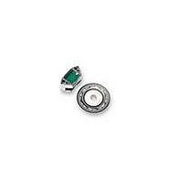
AEAS-7000-1GSG0 Avago Technologies US Inc., AEAS-7000-1GSG0 Datasheet - Page 2

AEAS-7000-1GSG0
Manufacturer Part Number
AEAS-7000-1GSG0
Description
IC ENCODER ABS 16BIT SERIAL
Manufacturer
Avago Technologies US Inc.
Series
AEAS-7000r
Datasheet
1.HEDS-8933.pdf
(8 pages)
Specifications of AEAS-7000-1GSG0
Pulses Per Revolution
1024
Termination Style
Terminal Pins
Encoder Type
Optical
Output Type
Gray Code (Absolute)
Voltage - Supply
5VDC
Actuator Type
10mm Dia Flatted End
Detent
No
Built In Switch
No
Mounting Type
Chassis Mount
Number Of Channels
14
Mounting Style
Through Hole
Output
Serial
Supply Voltage
5 V
Operating Temperature Range
- 25 C to + 85 C
Product
Optical
Lead Free Status / RoHS Status
Lead free / RoHS Compliant
Orientation
-
Rotational Life (cycles Min)
-
Lead Free Status / Rohs Status
Lead free / RoHS Compliant
Other names
516-2181
AEAS-7000-1GSG0
AEAS-7000-1GSG0
Signal-Channels A1-A11
The photocurrent of the photo diodes is fed into a
trans-impedance amplifier. The analog output of the
amplifier has a voltage swing of (dark/light) about 1.3
V.
comparators into digital signals (D1-D11). The
threshold is at VDD/2 (=Analog-reference), regulated
by the monitor channel.
Monitor Channel with LED Control at Pins LEDR and
LERR
The analog output signal of the monitor channel is
regulated by the LED current. An internal bipolar
transistor sets this level to VDD/2 (control voltage at
pin LEDR). Thus the signal swing of each output is
symmetrical to VDD/2 (=Analog-reference)
The error bit at pin LERR is triggered if the Ve of the
internal bipolar transistor is larger than VDD/2.
Signals Channels A0, A09 with Signal Conditioning and
Calibration
These two channels give out a sine and cosine wave,
which are 90 degree phase shifted. These signals have
amplitudes which are almost constant due to the LED
current monitoring.
mechanical misalignment, the signals have gain and
offset errors. These errors are eliminated by an adaptive
signal conditioning circuitry. The conditioning values
are on-chip preprogrammed by factory. The analog
output signals of A0 and A09 are supplied as true-
differential voltage with a peak to peak value of 2.0 V
at the pins A09P, A09N, A0P, A0N.
Interpolator for Channels A0,A09
The interpolator generates the digital signals D0,D09
and D-1 to D-4. The interpolated signals D-1 to D-4
extend the 12 bit Gray code of the signals D11….D0
to form a 16 bit Gray code.
D0 and D09 are digitized from A0 and A09. The
channels A0-A11 and A09 have very high dynamic
bandwidth, which allows a real time monotone 12 bit
Gray code at 12000 RPM.
The interpolated 16 bit Gray code can be used up to
1000 RPM only. At more than 1000 RPM, only the 12
bit Gray code from the MSB side can be used.
2
Every output is transformed by precision
Due to amplifier mismatch and
LSB Gray Code Correction (Pin KORR)
This function block synchronizes the switching points
for the 11 bit Gray code of the digital signals D1 to
D11 with D0 and D09 (digitized signal of A0 and A09).
This Gray code correction only works for the 12 bit
MSB(4096 steps per revolution).
The correction is not for the 4 excess interpolated bits
of the 16 bit Gray code.
Gray code correction can be switched on or off by
putting the pin KORR =1(on) or =0(off).
MSBINV and DOUT Pins
The serial interface consists of a shift register. The
most significant bit, MSB (D11) will always be sent first
to DOUT.
direction) by using pin MSBINV.
DIN and NSL Pins
The serial input DIN allows the configuration as ring
register for multiple transmissions or for cascading 2
or more encoders. DIN is the input of the shift register
that shifts the data to DOUT.
The NSL pin controls the shift register, to switch it
between load (1) or shift (0) mode. Under load mode,
DOUT will give the logic of the MSB, i.e., D11.
Under shift mode (0), coupled with the SCL, the register
will be clocked, and gives out the serial word output
bit by bit. As the clock frequency can be up to 16
MHz, the transmission of the full 16 bit word can be
done within 1µs.
Valid data of DOUT should be read when the SCL clock
is low. Please refer to timing diagram (Figure 3).
The MSB can be inverted (change code


