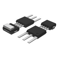
KMI15/4,115 NXP Semiconductors, KMI15/4,115 Datasheet - Page 4

KMI15/4,115
Manufacturer Part Number
KMI15/4,115
Description
SPEED SENSOR ROTATIONAL SOT453C
Manufacturer
NXP Semiconductors
Type
Special Purposer
Datasheet
1.KMI154115.pdf
(16 pages)
Specifications of KMI15/4,115
Sensing Range
0mm ~ 2.3mm
Voltage - Supply
5.5 V ~ 16 V
Current - Output (max)
8.4mA
Output Type
Digital, Open Collector
Features
Gear Tooth Type
Operating Temperature
-40°C ~ 85°C
Package / Case
SOT-453C
Maximum Operating Temperature
+ 85 C
Mounting Style
Through Hole
Lead Free Status / RoHS Status
Lead free / RoHS Compliant
Current - Supply
-
Lead Free Status / Rohs Status
Compliant
Other names
934050800115
KMI15/4 T/R
KMI15/4 T/R
KMI15/4 T/R
KMI15/4 T/R
Available stocks
Company
Part Number
Manufacturer
Quantity
Price
Part Number:
KMI15/4,115
Manufacturer:
NXP/恩智浦
Quantity:
20 000
Philips Semiconductors
FUNCTIONAL DESCRIPTION
The KMI15/4 sensor is sensitive to the motion of ferrous
gear wheels or reference marks. The functional principle is
shown in Fig.3. Due to the effect of flux bending, the
different directions of magnetic field lines in the
magnetoresistive sensor element will cause an electrical
signal. Because of the chosen sensor orientation and the
direction of ferrite magnetization, the KMI15/4 is sensitive
to movement in the ‘y’ direction in front of the sensor only
(see Fig.2).
The magnetoresistive sensor element signal is amplified,
temperature compensated and passed to a Schmitt-trigger
in the conditioning integrated circuit (Figs 4 and 5).
The digital output signal level (see Fig.6) is at a fixed level
independent of the sensing distance. A (2-wire) output
current enables safe sensor signal transport to the
detecting circuit (see Fig.7). The integrated circuit housing
is separated from the sensor element housing to optimize
the sensor behaviour at high temperatures.
The strength of the magnetic field caused by the
Ferroxdure 100 magnet in the different sensor directions,
measured at the centre of the magnetoresistive bridge, is
typically: H
(perpendicular to the sensor surface). H
trimming process.
2000 Sep 05
handbook, full pagewidth
Rotational speed sensor
x
sensor
= 7 kA/m (auxiliary field) and H
z
gear wheel
(a)
y
magnet
y
is zero due to the
z
= 17 kA/m
(b)
Fig.3 Functional principle.
field lines
magnetic
4
handbook, halfpage
y
Fig.2 Component detail of the KMI15/4.
(c)
x
direction
motion
of
magnet with
direction of
magnetization
sensor
IC
Product specification
x
(d)
KMI15/4
MBH779
z
MRA957


