NTCSMELFE3104JT Vishay, NTCSMELFE3104JT Datasheet

THERMISTOR NTC 100K 5% MELF

NTCSMELFE3104JT

Manufacturer Part Number
NTCSMELFE3104JT
Description
THERMISTOR NTC 100K 5% MELF
Manufacturer
Vishay
Series
2381r
Type
NTCr

Specifications of NTCSMELFE3104JT

Resistance In Ohms @ 25°c
100K
Resistance Tolerance
±5%
B Value Tolerance
±1.3%
B25/85
3997K
Operating Temperature
-40°C ~ 200°C
Power - Max
100mW
Mounting Type
Surface Mount
Package / Case
MELF
Description Of Terminals
Leadless
Mounting Style
Surface Mount
Pin Count
2
Screening Level
Automotive
Sensitivity Index
3977K
Resistance @ 25c
100kohm
Thermal Time Constant
6s
Percentage Of Resistance Tolerance @ 25c
±5
Accuracy
±1.3
Operating Temperature Min Deg. C
-40C
Operating Temperature Max Deg. C
150C
Product Length (mm)
3.5mm
Product Height (mm)
1.7mm
Product Depth (mm)
1.7mm
Resistance
100 KOhms
Tolerance
5 %
Termination Style
Axial
Lead Free Status / RoHS Status
Lead free / RoHS Compliant
B0/50
-
B25/50
-
B25/75
-
B25/100
-
Lead Length
-
Lead Free Status / Rohs Status
Lead free / RoHS Compliant
Other names
2381 633 53104
2381 633 53104
238163353104
BC2545TR
Document Number: 29119
Revision: 23-Nov-09
PARAMETER
Temperature range
Resistance value at 25 °C
(R
Tolerance on R
B
Tolerance on B
Deviation in resistance value
due to B-tolerance
Ratio R
Rated dissipation
Dissipation factor
Response time
Thermal time constant
Temperature coefficient
Climatic category
Weight
ELECTRICAL DATA AND ORDERING INFORMATION
QUICK REFERANCE DATA
25/85
25
)
- value
(k )
T
R
100
10
20
30
/R
25
25
25/85
25
- value
- value
SMD MELF SOD80, Glass Encapsulated
B
3977K ± 1.3 %
3977K ± 1.3 %
3977K ± 1.3 %
3977K ± 1.3 %
25/85
Intermediate Temperatures table
See Resistance Values at
- VALUE
- 40 C to + 150 C
10 k to 220 k
2381 633 5....
2.5 mW/K
40/155/56
100 mW
VALUE
± 1.3 %
3977K
± 5 %
For technical questions, contact:
0.9 s
0.03 g
6 s
NTC Thermistor
12NC ORDERING CODE
2381 633 53..
FEATURES
APPLICATIONS
Temperature measurement, sensing and control:
DESIGN-IN SUPPORT
For complete Curve Computation, visit:
www.vishay.com/thermistors/curve-computation-list/
DESCRIPTION
These thermistors have a negative temperature coefficient
and are mounted in a glass envelope with two tinned
electrodes.
MOUNTING
By soldering.
2381 633 5..../NTCSMELFE3....T
103
203
303
104
Small diameter down to 1.7 mm
Quick response time down to 0.9 s
Wide temperature range from - 40 C to + 150 C
Resistant to corrosive atmospheres and harsh
environments
Old part number was 2322 633 5....
Component in accordance to RoHS 2002/95/EC and
WEEE 2002/96/EC
Available on tape
Domestic appliances
Automotive systems
Industrial process control
nlr@vishay.com
Vishay BCcomponents
SAP MATERIAL NO.
NTCSMELFE3...
103JT
203JT
303JT
104JT
www.vishay.com
59

Related parts for NTCSMELFE3104JT

NTCSMELFE3104JT Summary of contents

Page 1

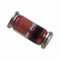
... These thermistors have a negative temperature coefficient 6 s and are mounted in a glass envelope with two tinned electrodes. 40/155/56 MOUNTING 0. soldering. 12NC ORDERING CODE 2381 633 53.. 103 203 303 104 For technical questions, contact: nlr@vishay.com Vishay BCcomponents SAP MATERIAL NO. NTCSMELFE3... 103JT 203JT 303JT 104JT www.vishay.com 59 ...

Page 2

... Vishay BCcomponents DIMENSIONS in millimeters DERATING Derating curve for 2381 633 5.... series STABILITY CHARACTERISTICS Stability of glass encapsulated NTCs in thermal shock test (200 kcycles - 40 °C/+ 200 °C) 0.8 ΔR R (%) 0.6 0.4 0 www.vishay.com 60 SMD MELF SOD80, Glass Encapsulated NTC Thermistor Component outline for 2381 633 5.... (SOD80) Ø ...

Page 3

... For technical questions, contact: nlr@vishay.com Vishay BCcomponents R/R T (± %) (%/K) (± K) 10.08 - 6.62 1.52 9.59 - 6.39 1.50 9.12 - 6.18 1.48 8.67 - 5.98 1.45 8.24 - 5.78 1 ...

Page 4

... Vishay BCcomponents PACKAGING BLISTER TAPE AND REEL (2381 633 5....) Packed wide blister tape, according to IEC60286 BLISTER TAPE AND REEL DIMENSIONS SYMBOL Blister tape K P OCKET APE T W www.vishay.com 62 SMD MELF SOD80, Glass Encapsulated NTC Thermistor 5° max. W Direction of unreeling ...

Page 5

... Vishay disclaims any and all liability arising out of the use or application of any product described herein or of any information provided herein to the maximum extent permitted by law. The product specifications do not expand or otherwise modify Vishay’ ...

Related keywords