QS30LDLQ BANNER ENGINEERING, QS30LDLQ Datasheet - Page 6
QS30LDLQ
Manufacturer Part Number
QS30LDLQ
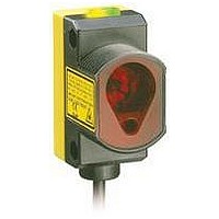
Description
Photoelectric Sensor
Manufacturer
BANNER ENGINEERING
Type
Laserr
Specifications of QS30LDLQ
Output Current
150mA
Sensor Output
NPN/PNP
Supply Voltage Range Dc
10V To 30V
Sensor Housing
Rectangular
Sensor Input
Laser
Body Material
ABS Plastic
Supply Voltage Max
30VDC
Sensing Range Max
800mm
Brand/series
QS30
Current, Switching
150 mA
Function
Proximity
Ip Rating
IP67
Mounting Type
Threaded
Output
NPN/PNP
Primary Type
Photoelectric
Range, Measurement
800 mm
Sensing Mode
Diffuse
Technology
Photoelectric
Termination
5-Wire Connector
Voltage, Supply
30 VDC
Lead Free Status / Rohs Status
RoHS Exempt Product


WORLD-BEAM
RUN Mode
• Lighted bargraph segment represents relative distance from the cutoff point.
• All segments OFF: No object is detected within the visible range.
SET Mode
• Segments 7 and 8 alternately flashing: Background Suppression SET is active
• Segments 5 and 6 alternately flashing: Object Detection SET is active
• Segments 1 and 8 alternately flashing: Dynamic SET is active
SET Mode Feedback
If the cutoff point is accepted, the sensor returns immediately to RUN mode. If the
taught cutoff point is beyond sensor range (closer than 50 mm or farther than
300 mm), the following are indicated for 2 seconds. (The sensor defaults to either
maximum or minimum cutoff, then returns to RUN mode.)
• Segments 7 and 8 simultaneously flashing: Indiscernible target; either no target or
• Segments 1 and 2 simultaneously flashing: Target is nearer than minimum cutoff.
SETUP mode (accessible via push buttons only) is used to change sensor output
response for:
• Normally Closed or Normally Open operation
• 30-millisecond pulse stretcher (OFF-delay), if required
The status LEDs, active only during SETUP mode, indicate the output response
configuration when the sensor will be in RUN mode. Four combinations are possible:
To access SETUP mode and change the output response settings:
NOTE: Outputs are active during SETUP mode.
In addition to its configuration function, the remote wire may be used to disable
the push buttons for security. Disabling the push buttons prevents accidental or
unauthorized adjustment of the sensor settings. Connect the gray wire of the sensor as
described on page 3, and four-pulse to either enable or disable the push buttons:
6
a highly reflective target (see page 7). Sensor defaults to maximum cutoff.
Sensor defaults to minimum cutoff.
Normally Open, No Delay
Normally Closed, No Delay
Normally Open, 30 ms Delay
Normally Closed, 30 ms Delay
1) Press and hold BOTH push buttons simultaneously until the green LED indicator
2) Click EITHER push button to toggle through the four possible setting
3) Sensor returns to RUN mode after push buttons are inactive for 4 seconds.
P/N 111384 rev. D
turns OFF.
combinations.
T
T
Bar Graph Indicator Functions
®
QS30AF Adjustable-Field Sensor
Push Button Disable
T T T
T
T
SETUP Mode
T
T
T
T
T
T
T
T
Banner Engineering Corp.
www.bannerengineering.com • Tel: 763.544.3164
Figure 6. SETUP mode
Indicators
SETUP
Status
{
•
Minneapolis, MN U.S.A.
Press and
hold
both push
buttons
to access
SETUP
mode
Related parts for QS30LDLQ
Image
Part Number
Description
Manufacturer
Datasheet
Request
R

Part Number:
Description:
QS30LD CLASS 1 LASER DIFFUSE
Manufacturer:
BANNER ENGINEERING
Datasheet:
Part Number:
Description:
QS30LD-16189 4PIN PICO 8IN 225uS RESPONSE INTEVAC P/N: 00839093-11
Manufacturer:
BANNER ENGINEERING

Part Number:
Description:
Photoelectric Sensor
Manufacturer:
BANNER ENGINEERING
Datasheet:

Part Number:
Description:
Photoelectric Sensor
Manufacturer:
BANNER ENGINEERING
Datasheet:
Part Number:
Description:
LEDIR70XD4-XM-81039 MAX INTENS STROBE ONLY NO BANNER MARKS
Manufacturer:
BANNER ENGINEERING
Part Number:
Description:
M18SP6DL-72225 LABELED MOELLER NO BANNER MARKINGS BULK PACK
Manufacturer:
BANNER ENGINEERING
Part Number:
Description:
M18SP6DLQ-72226 LABLED MOELLER NO BANNER MARKINGS BULK PACK
Manufacturer:
BANNER ENGINEERING
Part Number:
Description:
M18SP6L-72223 LABELED MOELLER NO BANNER MARKINGS BULK PACK
Manufacturer:
BANNER ENGINEERING
Part Number:
Description:
Photoelectric Sensor
Manufacturer:
BANNER ENGINEERING
Datasheet:

Part Number:
Description:
Programmable Indicator Light
Manufacturer:
BANNER ENGINEERING
Datasheet:
Part Number:
Description:
INDICATOR LED PANEL 50MM GRN/RED/YEL 30V
Manufacturer:
BANNER ENGINEERING
Datasheet:
Part Number:
Description:
Programmable Indicator Light
Manufacturer:
BANNER ENGINEERING
Datasheet: