IFMR0036 Red Lion Controls, IFMR0036 Datasheet - Page 4
IFMR0036
Manufacturer Part Number
IFMR0036
Description
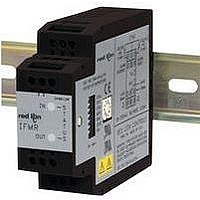
Isolation Amplifier
Manufacturer
Red Lion Controls
Type
Speedr
Specifications of IFMR0036
Width
3.12"
Signal Input Type
Selectable Current Or Voltage
Configuration Setup
DIP Switch
Supply Voltage Max
32VDC
Iso-amp Mounting Type
DIN Rail
Display Alarm Type
Relay
Input Accuracy
± 0.1% Of FS
Application
The IFMR utilizes a seven position DIP switch, a rotary switch, a pushbutton and two indication LEDs to accomplish input circuit configuration, operational parameter set-up, input signal, and relay status indication
Brand/series
IFMR Series
Contact Form
SPDT
Current Rating
5 A
Dimensions
27.5mmW×4.2mmH×79.2mmD
Display Type
LED
Input Type
Analog
Mounting Type
DIN Rail
Output Type
Relay
Power, Rating
2 W
Primary Type
Controller
Sensor, Input
12 VDC
Standards
cURus, CE
Temperature, Operating
0 to +50 °C
Termination
Screw
Voltage, Rating
9 to 32 VDC
Voltage, Supply
9-32 VDC
Signal Output Type
Current
Rohs Compliant
Yes
Lead Free Status / RoHS Status
Lead free / RoHS Compliant
For Use With
Sensors/Switches/TTL


INPUT CIRCUITS, SENSOR CONNECTIONS AND CONFIGURATION SWITCH SET-UP
Note: Separate power supplies must be used for sensor power and input power to maintain the isolation breakdown voltage specification. If isolation between power
OUTPUT
Schmidt trigger circuit to convert the input wave form into the pulse form
required for proper circuit operation. Three set-up switches are used to configure
the input circuit to accept signals from a wide variety of sources, as follows:
S1 - ON: Connects a 1 K pull-down resistor for sensors with sourcing
SENSOR
-EF
OUTPUT
MAGNETIC PICKUPS
RECOMMENDED RULES FOR MAGNETIC PICKUP CONNECTIONS
1. Connect the shield to the common Terminal “9” at the input of the IFMR. DO NOT
2-WIRE PROXIMITY SENSORS
OLDER STYLE RLC SENSORS WITH -EF OUTPUT
INPUT FROM CMOS OR TTL
RLC
SENSOR
MODELS
PSA-1
PSA-2
GREEN
RED
LED
INPUT
and input is not needed, then a single supply can be used for both unit and sensor power.
The Model IFMR Speed Switch uses a comparator amplifier connected as a
LED
connect the shield at the pickup end. Leave the shield “open” at the pickup and insulate
the exposed shield to prevent electrical contact with the frame or case. (Shielded cable,
supplied on some RLC magnetic pickups, has open shield on pickup end.)
DIP SWITCH
MAGNETIC PICKUP
BLU
BLK OR BRN
outputs. (Maximum sensor output current is 24 mA @ 24 VDC
output.)
4
4
4
4
4
4
AC VERSION
AC VERSION
O U
B
5
5
5
5
5
5
A
C
I N
T
6
6
6
6
6
6
7
7
7
7
7
7
CONNECTIONS & CONFIGURATION SWITCH SET-UP FOR VARIOUS SENSOR OUTPUTS
7
8
9
DESCRIPTION
Operating Mode
Set Trip Frequency Using an Input Signal or Frequency Generator
Set Trip Frequency Using the Rotary Switch
Set Minimum Response Time
Set Relay Trip Point
Set Relay Release Point
PUSHBUTTON
+12 V
COMM.
+12 V
COMM.
INPUT
INPUT
SWITCHES
ROTARY
SWITCH
DIP
ON 1 2 3
ON 1 2 3
CONFIGURING THE IFMR
of “1” is indicated by one blink (½ sec on, ½ sec off), through a setting of “9”, which is indicated by nine blinks. A setting
of “0” is indicated by a single short flash (40 msec on, 1 sec off). After the entire value is indicated, the IFMR pauses two
seconds and repeats the value.
button is pressed, the IFMR aborts the entry process and retains the previous setting.
Upon entry to a set-up parameter, the Input LED blinks the current numerical value of a setting at a 1 Hz rate. A setting
During entry of a new value, if the Mode switch (S4) or any of the CFG DIP switch positions are changed before the push
To begin set-up, place DIP switch 4 to the on (up) position. DIP switches 5, 6, and 7 access unit configuration settings.
*
RLC
SENSOR
MODELS
PSA-1
PSA-2
Check sensor power requirements before
wiring.
*
Check sensor power requirements before
wiring.
SENSOR
-EF
OUTPUT
+12V
COMM.
INPUT
BLK OR BRN
BLU
DC VERSION
DC VERSION
A
C
B
*
ON 1 2 3
*
8
9
8
9
EXT. VDC+
EXT. VDC-
EXT. VDC+
EXT. VDC-
INPUT
INPUT
COMM.
COMM.
4
MACHINE GROUND
RLC SENSOR MODELS:
SENSOR
NPN O.C.
OUTPUT
PNP O.C.
OUTPUT
SENSOR
SENSORS WITH CURRENT SINK OUTPUT (NPN O.C.)
SENSORS WITH CURRENT SOURCE OUTPUT (PNP O.C.)
SWITCH CONTACT INPUT
ASTC, LMPC, PSAC, ZCG, ZFG, ZGG, ZHG, ZBG
CONTACT
S2 - ON: For logic level signals, sets the input bias levels to V
S3 - ON: Connects a 3.9 K pull-up resistor for sensors with current sinking
OFF: For increased sensitivity when used with magnetic pickups, sets the
1.8K
AC VERSION
AC VERSION
AC VERSION
V
input bias levels to V
output. (Max. sensor current = 3 mA.)
+12V
OUTPUT
COMM.
RED
WHT
BLK
10µF
IH
SECTION
1.8K
= 3.0 V.
(1.0)
(2.0)
(3.0)
(4.0)
(5.0)
(6.0)
+12 V
COMM.
INPUT
+12 V
COMM.
INPUT
+12 V
COMM.
INPUT
Note: To return to normal operation,
( ) Indicates Configuration Section
IL
ON 1 2 3
= 0.25 V, V
place DIP switch 4 in the down
(RUN) position.
ON 1 2 3
ON 1 2 3
CONTACT
MACHINE GROUND
SENSOR
PNP O.C.
OUTPUT
IH
*
NPN O.C.
OUTPUT
SENSOR
Check sensor power requirements before
wiring.
*
*
Check sensor power requirements before
wiring.
= 0.75 V.
Check sensor power requirements before
wiring.
1.8K
10µF
+12V
OUTPUT
COMM.
DC VERSION
DC VERSION
DC VERSION
RED
WHT
BLK
1.8K
*
*
8
9
IL
8
9
EXT. VDC+
EXT. VDC-
8
9
EXT. VDC+
EXT. VDC-
INPUT
COMM.
EXT. VDC+
EXT. VDC-
= 2.5 V,
INPUT
COMM.
INPUT
COMM.
Related parts for IFMR0036
Image
Part Number
Description
Manufacturer
Datasheet
Request
R

Part Number:
Description:
Counter
Manufacturer:
Red Lion Controls
Datasheet:
Part Number:
Description:
Miniature Length Sensor
Manufacturer:
Red Lion Controls
Datasheet:
Part Number:
Description:
Model Lsc - Single Channel Output Length Sensor
Manufacturer:
Red Lion Controls
Datasheet: