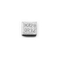
SMD150F-2018-2 Tyco Electronics, SMD150F-2018-2 Datasheet - Page 17

SMD150F-2018-2
Manufacturer Part Number
SMD150F-2018-2
Description
FUSE, PTC RESET, 15V, 1.5A, 2018
Manufacturer
Tyco Electronics
Series
MidSMDr
Specifications of SMD150F-2018-2
Holding Current
1.5A
Tripping Current
3A
Initial Resistance Max
0.18ohm
Operating Voltage
15VDC
Ptc Fuse Case
2018
Initial Resistance Min
0.07ohm
R Min/max
0.070 ~ 0.180 Ohm
Voltage - Max
15V
Time To Trip
1s
Current - Hold (ih) (max)
1.5A
Current - Trip (it)
3A
Current - Max
40A
Package / Case
2018
Hold Current
1.5 Amps
Trip Current
3 Amps
Current Rating (max)
40 Amps
Resistance
0.18 Ohms
Maximum Voltage
15 VoltsDC
Termination Style
SMD/SMT
Mounting Style
SMD/SMT
Current Rating
40 Amps
Lead Free Status / RoHS Status
Lead free / RoHS Compliant
Lead Free Status / RoHS Status
Lead free / RoHS Compliant, Lead free / RoHS Compliant
Other names
RF0325-000
• Operation beyond maximum ratings or improper
• These devices are intended for protection
• TR and TS devices are not intended for contin-
• LVR Product Notes:
Definitions
I
device will not trip under specified conditions at
20°C unless otherwise specified.
I
be used to trip a PolySwitch device under
specified conditions.
V
dropped across a PolySwitch device
continuously in its tripped state under specified
fault conditions.
R
specified conditions measured 1 hour post trip or
post reflow.
R
automotive conditions specified in PS400
measured 1 hour after stress has been removed.
Rmax. Initial = Maximum device resistance
under specified conditions as supplied.
I
under specified conditions.
H
max.
T
use may result in device damage and possible
electrical arcing and flame.
against occasional overcurrent or overtemper-
ature fault conditions, and should not be used
when repeated fault conditions are anticipated.
uous utility line voltage such as 120/220V or
240V.
1. A PTC device is not a fuse—it is a nonlinear
thermistor that limits current. Because under a
fault condition all PTC devices go into a high
resistance state but not open circuit, hazardous
voltage may be present at PTC locations.
2. The devices are intended for protection
against occasional overcurrent or
overtemperature fault conditions and should not
be used when repeated fault conditions or
prolonged trip events are anticipated.
3. Please refer to the SCD for complete
information and applications limitations, which
can be obtained from product management
(650-361-6900) or the web:
www.circuitprotection.com/lvr/
max.
1
a
= Minimum current at which a device will trip
= Hold current—maximum current at which the
max. = Maximum device resistance under
max. = Maximum device resistance under
= The highest fault current that can safely
= The highest voltage that can safely be
WARNING!
Standard PolySwitch product families
include, RGEF, RHEF, RTEF, RUEF, RXEF,
LVR, SMDF, nanoSMDF, microSMDF,
miniSMDF, BBRF, LR4F, LTPF, SRPF,
VTPF, VLRF, VLPF, AHRF, AGRF, and
AHS. PolySwitch TS, TR and ASMD
product families offer a selected number of
RoHS compliant parts. In addition, special
devices, such as speaker devices (SPK),
terminal devices (TD) and custom chip
devices, can be manufactured to meet
performance requirements that could be
outside of the performance band of the
standard products listed in this short form
catalog. Please contact a Raychem Circuit
Protection Customer Service representative
to discuss your special product needs.
Voltage Rating for Telecom Devices
For Raychem Circuit Protection telecom
devices (TC, TGC, TRx, TSx) there are
two applicable voltage ratings. These are
V
help understand the nature of these two
different voltage ratings the following
definitions are provided:
V
conditions this is the highest voltage
that can be applied to the device at the
maximum current. Devices have been
designed to trip safely under higher power
level cross conditions, as listed above, to
assist equipment in meeting the
appropriate industry conditions.
V
this is the voltage we have used to obtain
component recognition under UL1434.
Most Raychem Circuit Protection devices
(TC, TGC, TRx, TSx) are certified at 60V
but can withstand higher V
TS600 product families are certified at
250V but can withstand higher V
Interrupt conditions as noted above.
For the purposes of this brochure we have
included in the table of electrical ratings
the more applicable V
max.
max.
max.
Operating and V
Interrupt: Under specified
Operating: For telecom devices
14
max.
max.
Interrupt value.
max.
Interrupt. To
TR600 and
max.
Agency approvals for PolySwitch devices:
PolySwitch devices, where appropriate,
have been tested and have gained the
following safety agency approvals:
• UL Component Recognition in Category
• CSA Component Acceptance Class
• TU ¨ V Rheinland Certification, PTC
®
XGPU2, Thermistor Type Devices
9073 32, Thermistors—PTC Type
Resistors
®


