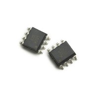
ACPL-0820-500E Avago Technologies US Inc., ACPL-0820-500E Datasheet

ACPL-0820-500E
Specifications of ACPL-0820-500E
Available stocks
Related parts for ACPL-0820-500E
ACPL-0820-500E Summary of contents
Page 1
... RoHS 6 fully compliant RoHS 6 fully compliant options available; -xxxE denotes a lead-free product Description ACPL-0820 is a high current dual line-driver IC. With single supply, it delivers up to 1.5 A for high current differential mode applications such as a Powerline modem. ACPL-0820 is internally protected against over-tempera- ture conditions through thermal shutdown and this status is reported by the Status pin ...
Page 2
... Out1 Vout 3 6 In2 Out2 -en Gnd ACPL-0820 R4 R1=R2, R3=R4, Overall Differential Output Status Vdd 2 7 In1 Out1 3 6 Vout In2 Out2 -en Gnd ACPL -0820 (R2/R1) V out out out1 Status Vdd 1Ω >1µ Vout In1 Out1 1Ω >1µ In2 Out2 I ...
Page 3
Package Pin Out Pin Descriptions Pin No. Vdd Status Out1 In1 2 7 Out2 In2 -en Gnd Block Diagram 1 Status 2 In1 V (2.25V) ...
Page 4
... Example 1: ACPL-0820-500E to order product of SO-8 package in Tape and Reel packaging and RoHS compliant. Option datasheets are available. Contact your Avago sales representative or authorized distributor for information. Remarks: The notation ‘#XXX’ is used for existing products, while (new) products launched since 15th July 2001 and RoHS compliant option will use ‘ ...
Page 5
Recommended Pb-free IR Profile 250 ° C 217 ° C 200 ° C 150 ° ° 150 sec Time (sec) Note: Non-halide flux should be used. Absolute Maximum Ratings Parameter Storage Temperature Ambient Operating Temperature ...
Page 6
Electrical Specifications Unless otherwise noted, for sinusoidal waveform input, all typical values are at T Maximum specifications are at Recommended Operating Limits. (Note: V Parameter Symbol V Supply Current Junction Over-Temperature Detection Threshold Junction Over-Temperature Shutdown Threshold ...
Page 7
Performance Plots Unless otherwise noted, all typical plots are at T (Note OL1 OL2 3 Idd/mA 2.5 2 1 TX-EN 0 -50 - ...
Page 8
Gain = - Ω out -70 -50 - Ta-Ambient Temperature - C ...
Page 9
... ASK, FSK and BPSK. Figure 17 shows a typical 2k7 STATUS C1 R1 TXp Filter 10k Ω 100nF C2 R2 TXn 10k Ω 100nF TX-EN PLM Transceiver Figure 17. Schematic of Isolated ACPL-0820 application for FSK modulation scheme 25° sinusoidal waveform input, and signal frequency 20k Ω I out1 5V 8 Scope R L1 100nF 7 V ...
Page 10
... The 2nd feature is load detection sensing feature. The pow- erline impedance is quite unpredictable and varies not just at different connection points but is also time variant. ACPL- 0820 includes this current sensing feature, which may be C3 (or C4) (nF) utilized to feedback information on the instantaneous pow- erline load conditions ...


