ADNS-3530 Avago Technologies US Inc., ADNS-3530 Datasheet - Page 6
ADNS-3530
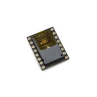
Manufacturer Part Number
ADNS-3530
Description
Small Form Factor COB LED Sensor
Manufacturer
Avago Technologies US Inc.
Datasheet
1.ADNS-3530.pdf
(25 pages)
Specifications of ADNS-3530
Lead Free Status / RoHS Status
Lead free / RoHS Compliant
Lead Free Status / RoHS Status
Lead free / RoHS Compliant


PCB Assembly Considerations
1. Surface mount the sensor and all other electrical com-
2. Reflow the entire assembly in a no-wash solder
3. Place the lens onto the base plate. Care must be taken
4. Remove the protective kapton tape from optical ap-
5. Insert PCB assembly over the lens onto the base plate
6. The optical position reference for the PCB is set by the
Figure 6a. Sectional view of PCB assembly
Figure 6b. Sectional view of PCB assembly highlighting optical mouse components
6
BOTTOM OF PCB TO
NAVIGATION SURFACE
CUSTOMER'S BASE PLATE
ponents into PCB.
process.
to avoid contaminating or staining the lens.
erture of the sensor and LED. Care must be taken to
keep contaminants from entering the aperture. Rec-
ommend not to place the PCB facing up during the
entire mouse assembly process. Recommend to hold
the PCB first vertically for the kapton removal process.
aligning post to retain PCB assembly. The lens piece
has alignment posts which will mate with the align-
ment holes on the sensor aperture.
base plate and lens. Note that the PCB motion due to
button presses must be minimized to maintain optical
alignment.
(0.13)
3.25
BOTTOM OF PCB TO
BOTTOM MATING
SURFACE OF LENS
CUSTOMER'S PCB
(0.09)
2.28
BOTTOM OF LENS
TO NAVIGATION SURFACE
(0.01)
0.29
LENS
CUSTOMER'S PCB
LED DIE
7. Install mouse top case. There MUST be a feature in the
Design Considerations for Improved ESD Performance
For improved electrostatic discharge performance, typi-
cal creepage and clearance distance are shown in the
table below. Assumption: base plate construction as per
the Avago Technologies supplied IGES file and ADNS-
3150-001 lens.
Typical Distance
Creepage
Clearance
Note that the lens material is polycarbonate and there-
fore, cyanoacrylate-based adhesives or other adhesives
that may damage the lens should NOT be used.
top case to press down onto the sensor to ensure the
sensor and lens components are interlocked to the
correct vertical height.
SENSOR DIE
NAVIGATION
SURFACE
LENS
NAVIGATION
SURFACE
SENSOR PCB
SENSOR
Millimeters
0.6
2.76
BOTTOM MATING SURFACE
OF LENS TO NAVIGATION SURFACE
(0.04)
0.97
CUSTOMER'S
BASE PLATE
(0.10)
2.50
DIE TO NAVIGATION
SURFACE
Related parts for ADNS-3530
Image
Part Number
Description
Manufacturer
Datasheet
Request
R

Part Number:
Description:
Optical Mouse Sensor,DIP
Manufacturer:
Avago Technologies US Inc.
Datasheet:

Part Number:
Description:
Optical Mouse Sensor,DIP
Manufacturer:
Avago Technologies US Inc.
Datasheet:

Part Number:
Description:
Trim Lens For ADNS-3530
Manufacturer:
Avago Technologies US Inc.
Datasheet:

Part Number:
Description:
8 DIP SFF Navigation Sensor
Manufacturer:
Avago Technologies US Inc.
Datasheet:

Part Number:
Description:
Trim Lens For ADNS-5090
Manufacturer:
Avago Technologies US Inc.
Datasheet:

Part Number:
Description:
BLACK CLIP FOR ADNS-5000
Manufacturer:
Avago Technologies US Inc.
Datasheet:
Part Number:
Description:
Lens For ADNS-7630
Manufacturer:
Avago Technologies US Inc.
Datasheet:

Part Number:
Description:
Optical Mouse Sensor,DIP
Manufacturer:
Avago Technologies US Inc.
Datasheet:

Part Number:
Description:
SENSOR OPTICAL MOUSE 8-DIP
Manufacturer:
Avago Technologies US Inc.
Datasheet:
Part Number:
Description:
Optical Mouse Sensor,DIP
Manufacturer:
Avago Technologies US Inc.
Datasheet:

Part Number:
Description:
OPTOCOUPLER GATE DRV 2A 16-SOIC
Manufacturer:
Avago Technologies US Inc.
Datasheet:
Part Number:
Description:
OPTOCOUPLER 2CH 2.5A 16-SOIC
Manufacturer:
Avago Technologies US Inc.
Datasheet:

Part Number:
Description:
OPTOCOUPLER GATE DRV 0.4A 16SOIC
Manufacturer:
Avago Technologies US Inc.
Datasheet:

Part Number:
Description:
OPTOCOUPLER 2.0A 250KHZ 8-DIP
Manufacturer:
Avago Technologies US Inc.
Datasheet:

Part Number:
Description:
OPTOCOUPLER 2.0A 250KHZ GW 8-SMD
Manufacturer:
Avago Technologies US Inc.
Datasheet: