HSMF-C114 Avago Technologies US Inc., HSMF-C114 Datasheet

Surface-Mount/Axial LED Lamp,Blue/Bl-Gr/Or-Red,Diffused,LED-8d

HSMF-C114

Manufacturer Part Number
HSMF-C114
Description
Surface-Mount/Axial LED Lamp,Blue/Bl-Gr/Or-Red,Diffused,LED-8d
Manufacturer
Avago Technologies US Inc.
Type
Tri-Colorr
Datasheet

Specifications of HSMF-C114

Color
Red, Green, Blue (RGB)
Millicandela Rating
85mcd Red, 180mcd Green, 70mcd Blue
Current - Test
20mA
Wavelength - Dominant
626nm, 525nm, 470nm
Wavelength - Peak
637nm, 523nm, 468nm
Voltage - Forward (vf) Typ
1.9V Red, 3.4V Green, 3.4V Blue
Lens Type
Diffused
Lens Style/size
Rectangle, 1.5mm x 1.1mm
Package / Case
0606 (1616 Metric)
Size / Dimension
1.60mm L x 1.50mm W
Height
0.35mm
Viewing Angle
140°, 145°, 145°
Mounting Type
Surface Mount
Resistance Tolerance
626nm, 525nm, 470nm
Package Type
Chip Led
Emitting Color
Blue/Green/Red
Luminous Intensity
70/180/85mcd
Test Current (it)
20mA
Forward Current
15mA
Dominant Wave Length
470/525/626nm
Forward Voltage
3.9/3.9/2.4V
Product Length (mm)
1.5mm
Product Height (mm)
0.35mm
Product Depth (mm)
1.6mm
Mounting
Surface Mount
Peak Wavelength
468/523/637nm
Shape Type
Rectangular
Chip Material
InGaN/InGaN/AlGaInP
Main Category
Chip LED
Number Of Elements
3
Pin Count
4
Operating Temperature Classification
Industrial
Operating Temp Range
-40C to 85C
Reverse Voltage
5V
Power Dissipation
78/78/48mW
Lens Dimensions
1.1X1.5X0.23mm
Lead Free Status / RoHS Status
Lead free / RoHS Compliant
Luminous Flux @ Current - Test
-
Lead Free Status / Rohs Status
Compliant
Other names
516-1795-2
HSMF-C114

Available stocks

Company
Part Number
Manufacturer
Quantity
Price
Part Number:
HSMF-C114
Manufacturer:
AVAGO
Quantity:
40 000
Part Number:
HSMF-C114
Manufacturer:
AVAGO
Quantity:
50 000
Part Number:
HSMF-C114
Manufacturer:
BROADCOM
Quantity:
20 000
HSMF-C114
Surface Mount Tricolor ChipLEDs
Data Sheet
Description
The HSMF-C114 tricolor chip-type LED is designed in an
ultra small package for miniaturiza-tion. It is the first of its
kind to achieve such small packaging and be the thinnest
package in the industry for tricolor package. With the free-
dom to have any combination of colors from mixing of the
3 primary colors, this will yield a wide variety of colors to
suit every application and product theme.
The small size, narrow footprint, and low profile make
this LED excellent for back-lighting, status indication, and
front panel illumination applications.
In order to facilitate pick and place operation, this ChipLED
is shipped in tape and reel, with 4000 units per reel. The
package is compatible with reflow soldering and binned
by both color and intensity.
CAUTION:
component to prevent damage and/or degradation which may be induced by ESD.
It is advised that normal static precautions be taken in handling and assembly of this
Features
x Common anode
x Small 1.6 x 1.5 x 0.35 mm package
x Diffused optics
x Red/Green/Blue color combination
x Available in 8 mm tape on 7" diameter reels
x High brightness using AlInGaP and InGaN die technology
x Compatible with reflow soldering
Applications
x Backlighting
x Status indicator
x Front panel indicator
x Office automation, home appliances, industrial
equipment

Related parts for HSMF-C114

HSMF-C114 Summary of contents

Page 1

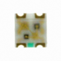
... HSMF-C114 Surface Mount Tricolor ChipLEDs Data Sheet Description The HSMF-C114 tricolor chip-type LED is designed in an ultra small package for miniaturiza-tion the first of its kind to achieve such small packaging and be the thinnest package in the industry for tricolor package. With the free- dom to have any combination of colors from mixing of the 3 primary colors, this will yield a wide variety of colors to suit every application and product theme ...

Page 2

Package Dimensions 2 ANODE MARK 1 1.60 (0.063) 1.10 (0.043) DIFFUSED EPOXY PC BOARD 0.40 0.15 (0.016 0.006) ANODE MARK NOTES: 1. ALL DIMENSIONS IN MILLIMETERS (INCHES). 2. TOLERANCE IS 0 0.004 IN.) UNLESS OTHERWISE SPECIFIED. Absolute Maximum ...

Page 3

Electrical Characteristics 25°C A Forward Voltage Part Number Typ. AlInGaP Red 1.9 InGaN Green 3.4 InGaN Blue 3.4 Note tolerance: ± 0.1 V. Optical Characteristics ...

Page 4

Light Intensity (I ) Bin Limits V Intensity (mcd) Bin ID Minimum A 0.11 B 0.18 C 0.29 D 0.45 E 0.72 F 1.10 G 1.80 H 2.80 J 4.50 K 7.20 L 11.20 M 18.00 N 28.50 P ...

Page 5

AlInGaP InGaN InGaN RED BLUE GREEN 0.8 0.6 0.4 0.2 0 400 450 500 550 600 650 700 WAVELENGTH – nm Figure 1. Relative intensity vs. wavelength ...

Page 6

Figure 8. Recommended soldering land pattern. 3.0±0.5 (0.118±0.020) 178.40±1 (7.024±0.039) 4.0±0.5 (0.157±0.020) Figure 10. Reel dimensions. 6 0.9 PRINTED LABEL Figure 9. Reeling orientation. Ø 13.1±0.5 (0.516±0.020) Ø 20.20 MIN. (0.795 MIN.) 5.0±0.5 (0.197±0.020) 6 ...

Page 7

... USER FEED DIRECTION TABLE 1 DIMENSIONS IN MILLIMETERS (INCHES) DIM. A DIM. B PART NUMBER ±0.10 (± 0.004) ±0.10 ( ±0.004) HSMF-C114 1.75 (0.069) 1.65 (0.065) START THERE SHALL BE A MINIMUM OF MINIMUM OF 160 mm 230 mm (6.3 INCH) OF EMPTY (9.05 INCH) COMPONENT POCKETS MAY CONSIST ...

Related keywords