FLEX104 EVIDENCE, FLEX104 Datasheet - Page 25
FLEX104
Manufacturer Part Number
FLEX104
Description
Development Tools & Eval/Demo Boards
Manufacturer
EVIDENCE
Datasheet
1.FLEX103.pdf
(41 pages)
Specifications of FLEX104
Silicon Manufacturer
Microchip
Application Sub Type
FLEX Multibus RS485 Module
Kit Application Type
Communication & Networking
Kit Contents
Board
Supply Voltage Range
7V To 12V, 9V To 36V
Lead Free Status / RoHS Status
Lead free / RoHS Compliant


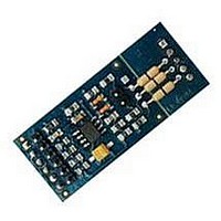
Figure 3.15: A photo of the Multibus base board (the color of the production board is
a base board where different communication modules can be plugged in, to adapt the
communication available on the board to the application requirements. The Multibus
board provides the transceivers to the most common interfaces available on the dsPIC
chip, like serials, SPI, CAN I2C, as well as additional enhancements like the ethernet
port.
has to be plugged on top of a FLEX Light or a FLEX Full by using the connectors on the
FLEX boards. The base board contains a set of jumpers which are needed to configure
the different communication devices, as well as a set of “slots” for plug-in modules, and
a set of clamps for the connection to the communication buses.
numbers 1 and 2 are serial modules, 3 and 4 are CAN modules, 5 is left empty, 6 is
an SPI module, 7 and 8 are the ethernet modules and connector. Please note that the
Ethernet connector is typically not mounted on the Multibus base board.
of the various modules.
The Multibus daughter board is composed bye a base board (see Figure 3.15) which
Figure
Figure
The following plug-in modules are available to the final user:
• UART TTL (see Subsection 3.3.2);
3.17
3.16
blue).
shows the location of the various plugin modules to simplify the placing
shows the multibus board mounted on a FLEX board. In the figure,
25
Related parts for FLEX104
Image
Part Number
Description
Manufacturer
Datasheet
Request
R

Part Number:
Description:
FLEX Light Base Board
Manufacturer:
EVIDENCE
Datasheet:

Part Number:
Description:
FLEX MultiBus Daughter Board
Manufacturer:
EVIDENCE
Datasheet:

Part Number:
Description:
FLEX Demo Daughter Board
Manufacturer:
EVIDENCE
Datasheet:

Part Number:
Description:
FLEX Full Base Board
Manufacturer:
EVIDENCE
Datasheet:

Part Number:
Description:
FLEX Blank Thru-Hole Daughter Board
Manufacturer:
EVIDENCE
Datasheet:

Part Number:
Description:
FLEX Multibus Ethernet Module
Manufacturer:
EVIDENCE
Datasheet:

Part Number:
Description:
FLEX Multibus RS232 Module
Manufacturer:
EVIDENCE
Datasheet:

Part Number:
Description:
FLEX Multibus RS422 Module
Manufacturer:
EVIDENCE
Datasheet:

Part Number:
Description:
FLEX Multibus CAN Module
Manufacturer:
EVIDENCE
Datasheet:

Part Number:
Description:
FLEX Multibus SPI Module
Manufacturer:
EVIDENCE
Datasheet:


Part Number:
Description:
Microcontroller & Microprocessor Development Tools Demo2 Pack
Manufacturer:
EVIDENCE
Datasheet:

Part Number:
Description:
Microcontroller & Microprocessor Development Tools Mini Kit
Manufacturer:
EVIDENCE
Datasheet:

Part Number:
Description:
Microcontroller & Microprocessor Development Tools Multibus Pack
Manufacturer:
EVIDENCE
Datasheet: