FLEX104 EVIDENCE, FLEX104 Datasheet - Page 33
FLEX104
Manufacturer Part Number
FLEX104
Description
Development Tools & Eval/Demo Boards
Manufacturer
EVIDENCE
Datasheet
1.FLEX103.pdf
(41 pages)
Specifications of FLEX104
Silicon Manufacturer
Microchip
Application Sub Type
FLEX Multibus RS485 Module
Kit Application Type
Communication & Networking
Kit Contents
Board
Supply Voltage Range
7V To 12V, 9V To 36V
Lead Free Status / RoHS Status
Lead free / RoHS Compliant


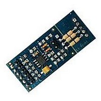
3 Architecture
Figure 3.24: The UART RS485 module.
Figure 3.25: The UART RS485 module layout.
• JP3 in position 1-2 enables the transmission (TX) from the signal TXEN of mi-
crocontroller (1 = ON); in position 2-3 enables the TX; if open disables the TX.
Figure
3.25
shows the module layout with the location of the various jumpers.
I2C module
This module can be used to connect in a safe way an I2C bus to one of the I2C peripherals
of the dsPIC. The protection includes protection from spikes, as well as hot inserction
and hot extractions.
SPI module
The module can be used to export one of the SPI peripheral pins which are available
on the dsPIC (see Figure 3.26). Moreover, the module has a set of components which
are used to protect the microcontroller pins from input signals which are not compatible
with the specifications.
The module has four jumpers named JP1, JP2, JP3 and JP4 which can be used to put
in high impedance respectively the digital output, clock, digital input and chip select
signals. Figure
3.27
shows the module layout with the location of the various jumpers.
33
Related parts for FLEX104
Image
Part Number
Description
Manufacturer
Datasheet
Request
R

Part Number:
Description:
FLEX Light Base Board
Manufacturer:
EVIDENCE
Datasheet:

Part Number:
Description:
FLEX MultiBus Daughter Board
Manufacturer:
EVIDENCE
Datasheet:

Part Number:
Description:
FLEX Demo Daughter Board
Manufacturer:
EVIDENCE
Datasheet:

Part Number:
Description:
FLEX Full Base Board
Manufacturer:
EVIDENCE
Datasheet:

Part Number:
Description:
FLEX Blank Thru-Hole Daughter Board
Manufacturer:
EVIDENCE
Datasheet:

Part Number:
Description:
FLEX Multibus Ethernet Module
Manufacturer:
EVIDENCE
Datasheet:

Part Number:
Description:
FLEX Multibus RS232 Module
Manufacturer:
EVIDENCE
Datasheet:

Part Number:
Description:
FLEX Multibus RS422 Module
Manufacturer:
EVIDENCE
Datasheet:

Part Number:
Description:
FLEX Multibus CAN Module
Manufacturer:
EVIDENCE
Datasheet:

Part Number:
Description:
FLEX Multibus SPI Module
Manufacturer:
EVIDENCE
Datasheet:


Part Number:
Description:
Microcontroller & Microprocessor Development Tools Demo2 Pack
Manufacturer:
EVIDENCE
Datasheet:

Part Number:
Description:
Microcontroller & Microprocessor Development Tools Mini Kit
Manufacturer:
EVIDENCE
Datasheet:

Part Number:
Description:
Microcontroller & Microprocessor Development Tools Multibus Pack
Manufacturer:
EVIDENCE
Datasheet: