LINKMATIK RF Solutions, LINKMATIK Datasheet - Page 4
LINKMATIK
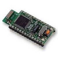
Manufacturer Part Number
LINKMATIK
Description
TRANSCEIVER, LINKMATIK, 18PIN, DIL
Manufacturer
RF Solutions
Datasheet
1.LINKMATIK.pdf
(11 pages)
Specifications of LINKMATIK
Svhc
No SVHC (15-Dec-2010)


Operating Modes
There are three operating modes for LinkMatik 2.0:
• Auto-Slave Mode, where LinkMatik 2.0 allows
• Auto-Master Mode, where LinkMatik 2.0 tries to
• Command Mode, where LinkMatik accepts
LinkMatik is shipped in Auto-Slave mode with the
PIN code 0000 (four zeroes).
Auto-Slave Mode
In Auto-Slave mode, LinkMatik 2.0 waits for a
remote device to discover and connect to it. No
commands are required, and, unless configuration
commands are sent, no responses are generated
except data from the remote device.
The ESC input would normally be tied low in Auto-
Slave mode unless configuration commands were
to be sent to LinkMatik 2.0.
The ATN output indicates whether the module is in
a connected state. The ATN output will be set
high when a connection is complete and low when
there is no connection. If data is sent while the
ATN is low, it will be interpreted as a command.
Page 4
TxD
Vdd
other devices to connect to it.
connect to devices it is paired with.
instructions from the host. Command mode is
also used for:
- Configuring Auto-Slave and Auto-Master
- Audio modes
- Connections to multiple devices
settings such as baud rates
For C = 100nF
Figure 3b. RS485 driver enable
7-Jul-06
9
10
1/2 74HC123
e.g. for 9600 baud, R ~ 27K
Vss
Vss
8,6
R
100nF
LinkMatik 2.0 DS379-1
=
C
Trig
250000
Baud
Clear
7
RC
11
R
Q
Q
22k
(K
Ω
16
Vdd
)
12
5
Vdd
RS485 DE
RC
© FlexiPanel Ltd
Auto-Master Mode
In Auto-Master mode, LinkMatik 2.0 searches for
any device it has in its list of paired devices and
connects to the first one it finds. A slave and a
master can thus be wedded and require no host
control. No commands are required, and, unless
configuration commands are sent, no responses
are generated except data from the remote device.
The ESC input would normally be tied low in Auto-
Master mode unless configuration commands
were to be sent to LinkMatik 2.0.
The ATN output indicates whether the module is in
a connected state. The ATN output will be set
high when a connection is complete and low when
there is no connection. If data is sent while the
ATN is low, it will be interpreted as a command.
Command Mode
In Command mode, commands are sent to
LinkMatik to control it.
required to configure Auto-Slave and Auto-Master
modes are detailed in this document.
Refer to the LinkMatik 2.0 Command Reference
DS389-1
commands available in command mode, including
audio mode commands.
Configuration Commands
Sending Configuration Commands
To send commands for configuration purposes (as
opposed to host control), connect LinkMatik to a
serial
HyperTerminal. Commands should be terminated
with carriage return and linefeed characters.
If required, FlexiPanel’s Pixie Config Tool can be
used to convert between USB and TTL serial
signals in order to make the connections. If used
to connect to the SO module, however, care
should be taken to clamp the TxD maximum
voltage to 3.3V using a circuit such as shown in
figure 4. The tool has no flow control, so CTS is
connected to RTS.
To ensure all commands take effect, reset
LinkMatik 2.0.
To see a list of all current settings, send the
following command:
SET
Patents apply and/or pending
terminal
for
complete
emulator
Only those commands
details
such
www.FlexiPanel.com
as
about
Windows
other
Related parts for LINKMATIK
Image
Part Number
Description
Manufacturer
Datasheet
Request
R

Part Number:
Description:
RF SOLUTIONS FOR TRANSPORTATION
Manufacturer:
Skyworks Solutions Inc


Part Number:
Description:
RF Switch SPDT 0MHz to 2GHz 27dB 8-Pin SOIC T/R
Manufacturer:
M/A-Com Technology Solutions
Datasheet:
Part Number:
Description:
RF Switch SPST 500MHz to 2GHz 40dB 8-Pin SOIC T/R
Manufacturer:
M/A-Com Technology Solutions
Datasheet:
Part Number:
Description:
RF Switch SPDT 100MHz to 4GHz 14dB 6-Pin SOT-6
Manufacturer:
Skyworks Solutions Inc
Datasheet:
Part Number:
Description:
RF Switch SPST 500MHz to 2.5GHz 10dB 6-Pin SOT-6
Manufacturer:
Skyworks Solutions Inc
Part Number:
Description:
RF Amp Module Single Power Amp 1.91GHz 4.2V 10-Pin MCM
Manufacturer:
Skyworks Solutions Inc
Datasheet:
Part Number:
Description:
RF Amp Chip Single Power Amp 2.5GHz 4.5V 16-Pin QFN T/R
Manufacturer:
Skyworks Solutions Inc
Datasheet:

Part Number:
Description:
IC ENCODER TRANSMITTER RF 8DIP
Manufacturer:
RF Solutions
Datasheet:

Part Number:
Description:
IC DECODER RECEIVER RF 18DIP
Manufacturer:
RF Solutions
Datasheet:

Part Number:
Description:
IC ENCODER 3 DGTL I/O SOT23-6
Manufacturer:
RF Solutions
Datasheet:

Part Number:
Description:
IC ENCODER 3 DGTL I/O 8-PDIP
Manufacturer:
RF Solutions
Datasheet:

Part Number:
Description:
IC DECODER 3 DGTL I/O 8-PDIP
Manufacturer:
RF Solutions
Datasheet: