ETRX2HR-PA Telegesis Ltd, ETRX2HR-PA Datasheet
ETRX2HR-PA
Specifications of ETRX2HR-PA


Related parts for ETRX2HR-PA


ETRX2HR-PA Summary of contents
Page 1
... Telegesis ETRX2-PA, ETRX2HR-PA ETRX2-PA and ETRX2HR-PA ZIGBEE® MODULES ©2009 Telegesis (UK) Ltd PRODUCT MANUAL ETRX2PA Product Manual (Rev 1.07) TG-ETRX2PA-PM-003-107 Product Manual 1.07 ...
Page 2
... PRODUCT APPROVALS ..................................................................................................... 6 2.1 FCC Approvals................................................................................................................... 6 2.1.1 FCC Labelling Requirements............................................................................................. 7 2.2 European Certification ....................................................................................................... 7 2.3 Declarations of Conformity................................................................................................. 8 2.4 IEEE 802.15.4.................................................................................................................... 8 2.5 The ZigBee® Protocol ....................................................................................................... 8 3 MODULE PINOUT ................................................................................................................ 9 4 HARDWARE DESCRIPTION ............................................................................................. 11 4.1 Hardware Options ............................................................................................................ 11 4.1.1 On-board DC Regulator ................................................................................................... 11 4.1.2 On-board Reference Crystal ............................................................................................ 11 4.1.3 RF output pad .................................................................................................................. 11 5 HARDWARE INTERFACE ...
Page 3
APPLICATION NOTES ...................................................................................................... 27 17.1 Safety Precautions........................................................................................................... 27 17.2 Design Engineering Notes ............................................................................................... 27 17.3 Storage Conditions .......................................................................................................... 28 18 PACKAGING ...................................................................................................................... 29 18.1 Embossed Tape............................................................................................................... 29 18.2 Component Orientation.................................................................................................... 30 18.3 Reel Dimensions.............................................................................................................. 30 18.4 Packaging ........................................................................................................................ 30 ...
Page 4
... EmberNet meshing stack. • Can act as ZigBee End Device, Router or Coordinator • 12 general-purpose I/O lines and 2 analogue inputs (all 17 GPIOs of the EM250 are accessible) • Supports 4 different power modes • Current consumption below 1µA in deep sleep mode with self wakeup • ...
Page 5
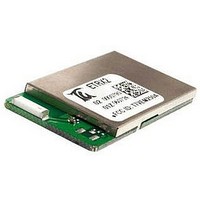
... This document describes the Telegesis ETRX2-PA ZigBee® module which has been designed to be integrated into another device and to provide a fast, simple and low cost wireless mesh networking interface. Unless clearly indicated, its contents also apply to the ETRX2HR-PA module with a Hirose U.FL coaxial antenna connector in place of the on-board ceramic antenna. The user cannot convert an ETRX2-PA into an ETRX2HR-PA or vice-versa. The Telegesis ETRX2-PA module is based on the Ember ZigBee® ...
Page 6
... While the applicant for a device into which the ETRX2-PA or ETRX2HR-PA (with an antenna listed in Table 1) is installed is not required to obtain a new authorization for the module, this does not preclude the possibility that some other form of authorization or testing may be required for the end product. © ...
Page 7
... FCC Labelling Requirements When integrating the ETRX2-PA or ETRX2HR-PA into a product if must be ensured that the FCC labelling requirements are met. This includes a clearly visible label on the outside of the finished product specifying the Telegesis FCC identifier (FCC ID: T7VEM250B) as well as the notice above. This exterior label can use wording such as “ ...
Page 8
... It is the basis for the open ZigBee® Protocol. 2.5 The ZigBee® Protocol The ZigBee® Protocol is a set of standards for wireless connectivity for use between any devices over short to medium distances. The specification was originally ratified in December 2004, paving the way for companies to start making low-power networks a reality. ZigBee® ...
Page 9
Module Pinout The ETRX2-PA is pin-compatible with the ETRX1, (NB: it has additional pins to the ETRX1). For all new designs using either ETRX1 or ETRX2 it is recommended that you use the ETRX2 footprint to ensure the option ...
Page 10
ETRX2 Pad ...
Page 11
Hardware Description VBAT LDO or DC converter integrated (optional) antenna PA Pad 2 rf terminal Rx/Tx selection, switch filtering and U.FL socket matching circuitry 4.1 Hardware Options Please contact the manufacturer if any of the options described below could ...
Page 12
... Antenna Matching is provided to match the radio to the integrated antenna optional external general purpose 2.4GHz antenna. The on board antenna is supplied by Johanson. For full data on the Johanson antenna please refer to [4]. The connector on the ETRX2HR-PA is Hirose part number U.FL-SMT-R. Power The module is able to operate from 3.5V down to 2.7V which makes it ideally suited for battery- powered applications ...
Page 13
... The ETRX2-PA firmware uses the meshing and self healing EmberZNet PRO stack to overcome many of the limitations of the tree network topology of the ZigBee® 2006 stack. Following further evolution of the ZigBee® mesh networking specification, Telegesis also offer firmware that implements the PRO feature set of ZigBee 2007 ...
Page 14
Software Interface Using the default firmware the ETRX2-PA is controlled using a simple AT-style command interface and (mostly) non-volatile S-Registers. Commands, please refer to the AT command dictionary document which corresponds to the firmware revision you intend to use. ...
Page 15
Absolute Maximum Ratings Supply: Inputs: Operating temperature: No. Item 1 Supply voltage Voltage on any I/O[11: SIF_CLK, SIF_MISO, SIF_MOSI, SIF_LOADB, RESET 3 Voltage applied to Vreg 4 Storage temperature range 5 Operating temperature range 6 Input RF ...
Page 16
No. Item 1 Supply voltage 2 RF Input Frequency 3 RF Input Power EM250 Tx power mode 4 setting EM250 Tx output power 5 setting EM250 Tx output power 6 setting(2) EM250 Tx output power 7 setting(2) Typical module output ...
Page 17
DC Electrical Characteristics VBAT = 3.3V, TAMB = 25°C, NORMAL MODE unless otherwise stated No. Item Module supply voltage 1 VBAT Internal regulated core 2 voltage Quiescent current, 3 excluding internal RC oscillator Quiescent current, including 4 32.768kHz oscillator ...
Page 18
A/D Converter Characteristics No. Item 1 A/D characteristics 2 A/D timing/performance characteristics 3 Reference Voltage 4 Maximum Input Voltage If a voltage higher than 1.2V is applied to any of the ADC inputs, the readings on the Note: other ...
Page 19
No. Receiver Output power at highest power setting normal mode 15 NORMAL MODE BOOST MODE 16 Output power at power setting -20dBm 17 Output power at lowest power setting 18 Error vector magnitude as per IEEE802.15.4 19 Carrier frequency error ...
Page 20
TX Power Characteristics The diagrams below show the typical output power and module current in dependency on module supply voltage and EM250 power setting in NORMAL MODE -10 -15 -20 -25 -30 -50 ...
Page 21
Physical Dimensions Symbol L Length of the module W Width of the module H Height of the module A1 Pitch A2 Distance centre of pad PCB edge A3 Distance centre of pad PCB edge A4 Distance PCB edge metal ...
Page 22
For ideal RF performance when using the on-board antenna, the antenna should be located at the corner of the carrier PCB. There should be no components, tracks or copper planes in the “keep- out” area which should be as large ...
Page 23
Soldering Temperature Time Profile (for reflow soldering) 13.1 For Leaded Solder Recommended temp. profile for reflow soldering Temp .[°C] 150 ±10°C 13.2 For Lead-free Solder Our used temp. profile for reflow soldering 230°C -250°C max. Temp .[°C] 150°C – ...
Page 24
Product Label Drawing The label dimensions are is 13.0mm x 18.5 mm. The label is suitable for reflow soldering. Imprint ETRX2-PA Module Name 0000001 Indication for the serial number. Date Code Production Date Code in the format YYMMDD, e.g. ...
Page 25
Recommended Footprint In order to surface mount the module, we recommend that you use pads which are 1.5mm wide and 1.7mm high, the extra height extending the pads shown in Figure 9 towards the outside of your layout. You ...
Page 26
Example carrier board Since the RF performance of the module with the on board antenna is strongly dependent on the proper location of the module on its carrier board, Figure 10 shows the reference carrier board which was used ...
Page 27
Reliability Tests The measurements were conducted after the module being exposed to room temperature and humidity for 1 hour. No Item 1 Vibration test 2 Shock test 3 Heat cycle test 4 Moisture test 5 Low temp. test 6 ...
Page 28
In liquid, such as water, salt water, oil, alkali, or organic solvent places where liquid ...
Page 29
Packaging 18.1 Embossed Tape (1) Dimension of the tape (EIAJ-tbd) (2) Cover tape reel strength (3) Empty pockets Empty pockets NB: Empty pockets in the component packed area shall be less than two per reel and those empty pockets ...
Page 30
Component Orientation Top cover tape shall not be found on reel holes and will not stick out from the reel Direction 18.3 Reel Dimensions (4) Quantity per reel: 400 pieces (5) Marking: Part No. / Quantity / Lot No. ...
Page 31
... Ordering Information Ordering/Product Code ETRX2-PA ETRX2HR-PA ETRX2DVKA ETRX2DVKA-Plus Notes: • Customers’ PO’s must state the Ordering/Product Code. • There is no “blank” version of the ETRX2-PA Module available. All Modules are pre- programmed with the Telegesis AT style command interpreter based on the EmberZNet stack ...
Page 32
Trademarks All trademarks, registered trademarks and products names are the sole property of their respective owners. 21 Disclaimer Product and company names and logos referenced may either be trademarks or registered trademarks of their respective companies. We reserve the ...
Page 33
... Datasheet EM250, Ember. [3] Datasheet U.FL-Series 2004.2 Hirose Ultra Small Surface Mount Coaxial Connectors - Low Profile 1.9mm or 2.4mm Mated Height [4] Johanson 2450AT43A100 Antenna datasheet [5] The ZigBee® specification 26 Contact Information Website: www.telegesis.com E-mail sales@telegesis.com Telegesis (UK) Limited 3, Abbey Barn Business Centre Abbey Barn Lane ...