SD6030-680-R COILTRONICS, SD6030-680-R Datasheet
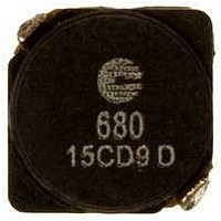
POWER INDUCTOR, 68UH

SD6030-680-R

Manufacturer Part Number
SD6030-680-R
Description
POWER INDUCTOR, 68UH
Manufacturer
COILTRONICS
Datasheet

Specifications of SD6030-680-R

Inductance Tolerance
± 30%
Dc Resistance Max
0.355ohm
Dc Current Rating
920mA
Core Material
Ferrite
Inductor Case Style
SMD
No. Of Pins
2
Inductor Type
Power
Saturation Current
0.52Arms
Inductance
68µH
Lead Free Status / RoHS Status
Lead free / RoHS Compliant
SD6030 Series
Low Profile Power Inductors
Description
• 125°C maximum total operating temperature
• Low profile surface mount inductors
• 6.0 x 6.0 x 3.0mm surface mount package
• Ferrite core material
• Shielded drum core reduces EMI
(1) Open Circuit Inductance Test Parameters: 100kHz, 0.1V, 0.0Adc.
(2) I rms : DC current for an approximate T of 40°C without core loss. Derating is necessary
(3) I sat amps peak for 35% rolloff (@25°C)
1207
Part Number
SD6030-2R7-R
SD6030-3R3-R
SD6030-4R2-R
SD6030-5R0-R
SD6030-5R8-R
SD6030-7R8-R
SD6030-100-R
SD6030-120-R
SD6030-150-R
SD6030-180-R
SD6030-220-R
SD6030-270-R
SD6030-330-R
SD6030-360-R
SD6030-440-R
SD6030-520-R
SD6030-680-R
SD6030-820-R
SD6030-101-R
SD6030-121-R
SD6030-151-R
SD6030-181-R
SD6030-221-R
for AC currents. Pad layout, trace thickness and width, airflow, and proximity of other heat
generating components will affect the temperature rise. It is recommended that the
temperature of the part not exceed 125°C under worst case operating conditions verified
in the end application.
BU-SB07328
Inductance
Rated
(µH)
100
120
150
180
220
2.7
3.3
4.2
5.0
5.8
7.8
10
12
15
18
22
27
33
36
44
52
68
82
µH ± 30%
OCL
110.1
144.5
175.7
210.9
11.3
14.1
17.1
20.4
26.0
32.4
34.4
44.0
52.0
65.6
81.6
94.4
2.7
3.3
4.1
4.9
5.8
7.8
9.3
(1)
Page 1 of 3
Irms
Amps
4.08
3.54
3.11
2.81
2.58
2.38
2.15
1.99
1.71
1.65
1.57
1.31
1.26
1.19
1.10
0.99
0.92
0.80
0.76
0.70
0.64
0.55
0.50
(2)
• Inductance range from 2.7µH to 680µH
• Current range from 0.16 amps to 4.08 amps
• Frequency range up to 1MHz
Applications
• Notebook computers, digital cameras
• DSL modems, PDAs
• High power LED driver
• MP3, CD players, GPS receivers
• Cellular phones, smart phones
• Wireless notebook adapters
• Battery power, TFT-LCD bias supplies
• PCMCIA, Cardbus32, MiniPCI cards
Environmental Data
• Storage temperature range: -40°C to +125°C
• Operating temperature range: -40°C to +125°C
• Solder reflow temperature: +260°C max. for 10 seconds maximum
Packaging
• Supplied in tape and reel packaging, 2000 per reel
(4) K-factor: Used to determine B p-p for core loss (see graph).
(5) Part Number Definition: SD6030-xxx-R
(range is application specific)
B p-p = K*L* I, B p-p(mT), K: (K factor from table), L: (Inductance in µH),
SD6030 = Product code and size; -xxx = Inductance value in µH;
R = decimal point; If no R is present, third character = # of zeros.
-R suffix = RoHS compliant
I (Peak to peak ripple current in amps).
Amps
Isat
2.60
2.40
2.20
1.90
1.80
1.60
1.30
1.20
1.10
1.00
0.90
0.85
0.75
0.70
0.62
0.58
0.52
0.46
0.42
0.40
0.35
0.32
0.30
(3)
m @20°C
(Typical)
1000
DCR
130
140
157
185
226
263
343
385
517
608
817
13
18
23
28
33
39
48
56
76
82
90
Data Sheet 4314
(Maximum)
m @20°C
1200
DCR
103
110
122
175
189
212
250
305
355
463
520
620
730
980
18
24
31
38
45
53
65
76
K-factor
9.3
8.7
7.9
7.2
6.5
5.9
5.6
5.6
5.0
4.5
4.0
34
30
27
24
22
19
17
16
14
13
12
11
(4)

Related parts for SD6030-680-R

SD6030-680-R Summary of contents

Page 1

... SD6030-150-R 15 SD6030-180-R 18 SD6030-220-R 22 SD6030-270-R 27 SD6030-330-R 33 SD6030-360-R 36 SD6030-440-R 44 SD6030-520-R 52 SD6030-680-R 68 SD6030-820-R 82 SD6030-101-R 100 SD6030-121-R 120 SD6030-151-R 150 SD6030-181-R 180 SD6030-221-R 220 (1) Open Circuit Inductance Test Parameters: 100kHz, 0.1V, 0.0Adc. (2) I rms : DC current for an approximate T of 40°C without core loss. Derating is necessary for AC currents. Pad layout, trace thickness and width, airflow, and proximity of other heat generating components will affect the temperature rise recommended that the temperature of the part not exceed 125° ...

Page 2

... K-factor: Used to determine B p-p for core loss (see graph). B p p-p(mT factor from table), L: (Inductance in µH), I (Peak to peak ripple current in amps). (5) Part Number Definition: SD6030-xxx-R SD6030 = Product code and size; -xxx = Inductance value in µ decimal point present, third character = # of zeros. -R suffix = RoHS compliant Front View Left View xxx = Inductance value in µ ...

Page 3

Temperature Rise vs. Loss Inductance Characteristics North America Cooper Bussmann Cooper Bussmann 1225 Broken Sound Parkway NW P.O. Box 14460 Suite F St. Louis, MO 63178-4460 Boca Raton, FL 33487-3533 Tel: 1-636-394-2877 Tel: 1-561-998-4100 Fax: 1-636-527-1607 Fax: 1-561-241-6640 Toll Free: ...

Related keywords