GP2W0110YPSF Sharp Microelectronics, GP2W0110YPSF Datasheet - Page 8
GP2W0110YPSF
Manufacturer Part Number
GP2W0110YPSF
Description
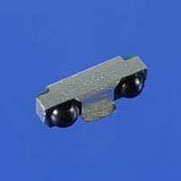
Fiber Optic Transmitters, Receivers, Transceivers GP2W0110YPSF Side View T&R
Manufacturer
Sharp Microelectronics
Datasheet
1.GP2W0110YPSF.pdf
(10 pages)
Specifications of GP2W0110YPSF
Product
Transceiver
Data Rate
115.2 Kbps
Wavelength
870 nm
Maximum Rise Time
600 ns, 60 ns
Maximum Fall Time
600 ns, 60 ns
Pulse Width Distortion
300 us, 6 us
Operating Supply Voltage
2 V to 3.6 V
Maximum Operating Temperature
+ 85 C
Minimum Operating Temperature
- 25 C
Idle Current, Typ @ 25° C
90µA
Link Range, Low Power
20cm
Operating Temperature
-25°C ~ 85°C
Orientation
Top View
Shutdown
*
Size
7.6mm x 2.65mm x 2mm
Standards
-
Supply Voltage
2 V ~ 3.6 V
Lead Free Status / RoHS Status
Lead free / RoHS Compliant
Available stocks
Company
Part Number
Manufacturer
Quantity
Price
Company:

Part Number:
GP2W0110YPSF
Manufacturer:
AVAGO
Quantity:
265


10-2. Designing IR Cosmetic Window
Following figure and calculation explain the example and designing hints for cabinet and IR cosmetic window with
+18
for design reference, and in mm (UNIT). The IrDA specifications require a +15
The +18
the required angle is always met.
The optical window size should be the minimum size of W x H rectangular or elliptical in order not to reduce IrDA
data transfer performance. The dimensions for W can be calculated by the formula of:
and the dimensions for H can be calculated by the formula of:
in case of having viewing angle of + 18, which conforms or exceeds the IrDA Serial Infrared Physical Layer Link
Specifications. Any values to be calculated with above formula must be given in mm.
The dimension “7.9” as listed above is the physical length of the transceiver. This distance includes the side
angles of the optical lenses to simplify the overall calculation. The height of the transceiver is 2.15 mm with the
shield however the actual transceiver face in the optical resin is 2.0 mm. These dimensions are listed in the
mechanical drawings.
Product Packaging
Many products that use infrared communication locate their reception component behind dark plastic. This often
fits in with the overall design and coloring of the product, and has an intentional design purpose as well.
The photodiode that is used in optical receivers is sensitive to a range of light wavelengths, not only the
wavelength intended for reception. Visible light has many component factors and sources in a room. The dark
plastic used in product faceplates can be formulated to act as a highpass filter, reducing the amount of visible light
and other wavelengths landing on the photodiode and raising the internal noise currents.
The reduction of unwanted wavelengths provides for a quieter and more sensitive receiver. The wavelength used
for IrDA Data communication is 880 nm. The characteristic of any plastic used in a final product should keep this
in mind and not attenuate this wavelength.
Glass and plastic filters are available on the market, and vendors carry plastic materials that may be cut, bent or
molded. The key to selecting a plastics vendor is to ask them about the wavelength characteristics of their
materials. The more they know, the more likely they will be able to help you in a knowledgeable manner when
working on both the industrial design and wavelength pass characteristics of your IR window. If the vendor does
not know what you are talking about, you need to find a more knowledgeable source for filter materials.
SHARP Electronic Components
Rev. 1.2
ELECTRONIC COMPONENTS
o
viewing angles, in vertical and horizontal axis. All values for the transceiver dimensions are applicable only
, March 7, 2002
o
angle shown is to provide a little extra clearance to allow for slight manufacturing variations and so that
W = 2 x L x tan18 + w
H = 2 x L x tan18 + h
18 °
(7.9)
w
W
18 °
L
IrDA Low Power Infrared Transceiver
L
h (2.0)
o
18 °
18 °
viewing angle at the transceiver.
H
8
Related parts for GP2W0110YPSF
Image
Part Number
Description
Manufacturer
Datasheet
Request
R

Part Number:
Description:
IC FLASH 32MBIT 110NS 56SSOP
Manufacturer:
Sharp Microelectronics
Datasheet:

Part Number:
Description:
IC FLASH 16MBIT 100NS 56TSOP
Manufacturer:
Sharp Microelectronics
Datasheet:

Part Number:
Description:
IC FLASH 64MBIT 120NS 56TSOP
Manufacturer:
Sharp Microelectronics
Datasheet:

Part Number:
Description:
IC FLASH 16MBIT 90NS 48TSOP
Manufacturer:
Sharp Microelectronics
Datasheet:
Part Number:
Description:
IC SRAM 16KBIT 100NS 24DIP
Manufacturer:
Sharp Microelectronics
Datasheet:
Part Number:
Description:
IC SRAM 16KBIT 100NS 24SOP
Manufacturer:
Sharp Microelectronics
Datasheet:
Part Number:
Description:
IC SRAM 64KBIT 100NS 28DIP
Manufacturer:
Sharp Microelectronics
Datasheet:
Part Number:
Description:
IC SRAM 64KBIT 100NS 28SOP
Manufacturer:
Sharp Microelectronics
Datasheet:
Part Number:
Description:
IC SRAM 64KBIT 100NS 28SOP
Manufacturer:
Sharp Microelectronics
Datasheet:
Part Number:
Description:
IC SRAM 256KBIT 70NS 28DIP
Manufacturer:
Sharp Microelectronics
Datasheet:
Part Number:
Description:
IC FLASH 8MBIT 90NS 48TSOP
Manufacturer:
Sharp Microelectronics
Datasheet:
Part Number:
Description:
IC FLASH 8MBIT 85NS 40TSOP
Manufacturer:
Sharp Microelectronics
Datasheet:
Part Number:
Description:
IC FLASH 8MBIT 85NS 40TSOP
Manufacturer:
Sharp Microelectronics
Datasheet:
Part Number:
Description:
IC FLASH 16MBIT 90NS 48TSOP
Manufacturer:
Sharp Microelectronics
Datasheet:
Part Number:
Description:
IC FLASH 16MBIT 70NS 56TSOP
Manufacturer:
Sharp Microelectronics
Datasheet: