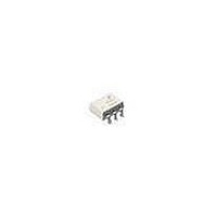
MOC3031SR2M Fairchild Semiconductor, MOC3031SR2M Datasheet - Page 7

MOC3031SR2M
Manufacturer Part Number
MOC3031SR2M
Description
Triac & SCR Output Optocouplers 6Pin250V Optocoupler Zero Cross Triac Dr
Manufacturer
Fairchild Semiconductor
Datasheet
1.MOC3031SM.pdf
(12 pages)
Specifications of MOC3031SR2M
Configuration
1
Maximum Input Current
60 mA
Maximum Operating Temperature
+ 85 C
Maximum Power Dissipation
250 mW
Maximum Reverse Diode Voltage
6 V
Minimum Operating Temperature
- 40 C
Output Type
AC
Package / Case
PDIP SMD White
Typical Input Voltage
1.25 V
Zero-crossing Circuit
Yes
Zero-crossing Voltage
20 V
Output Device
PhotoTriac
Isolation Voltage
7.5 kV
Peak Output Voltage (vdrm)
250 V
Maximum Input Voltage
1.5 V
Maximum Output Voltage
175 VAC
Minimum Trigger Current
15 mA (Max)
Lead Free Status / RoHS Status
Lead free / RoHS Compliant
Other names
MOC3031SR2M_NL
Available stocks
Company
Part Number
Manufacturer
Quantity
Price
Part Number:
MOC3031SR2M
Manufacturer:
FAIRCHILD/仙童
Quantity:
20 000
©2005 Fairchild Semiconductor Corporation
MOC303XM, MOC304XM Rev. 1.0.7
Typical circuit (Fig 12, 13) for use when hot line switching is required. In this circuit the “hot” side of the line is switched
and the load connected to the cold or neutral side. The load may be connected to either the neutral or hot line.
R
the MOC3032M and MOC3042M, or 15mA for the MOC3031M and MOC3041M. The 39 ohm resistor and 0.01µF
capacitor are for snubbing of the triac and may or may not be necessary depending upon the particular triac and
load used.
V
+250 for MOC303XM
+400 for MOC304XM
CC
in
APPLIED VOLTAGE
0 VOLTS
is calculated so that I
WAVEFORM
*
For highly inductive loads (power factor < 0.5), change this value to 360 ohms.
R
in
PULSE
Vdc
INPUT
Figure 12. Hot-Line Switching Application Circuit
1
2
3
RC
(MOC3031M, MOC3032M, MOC3033M)
(MOC3031M, MOC3032M, MOC3033M)
Figure 10. Static dv/dt Test Waveform
MOC3031M
MOC3032M
MOC3033M
158 V
MERCURY
Figure 9. Static dv/dt Test Circuit
WETTED
RELAY
F
R
TEST
6
is equal to the rated I
5
4
1 k
180
C
TEST
D.U.T.
D.U.T.
R = 10 k
39
0.01
V max = 250 V
dv/dt =
SCOPE
PROBE
*
LOAD
X100
0.63 V max
FT
RC
of the part, 5mA for the MOC3033M and MOC3043M, 10mA for
HOT
NEUTRAL
115 VAC
=
158
RC
1. The mercury wetted relay provides a high speed repeated
2. 100x scope probes are used, to allow high speeds and
3. The worst-case condition for static dv/dt is established by
7
pulse to the D.U.T.
voltages.
triggering the D.U.T. with a normal LED input current, then
removing the current. The variable R
to be gradually increased until the D.U.T. continues to
trigger in response to the applied voltage pulse, even after
the LED current has been removed. The dv/dt is then
decreased until the D.U.T. stops triggering.
measured at this point and recorded.
V
APPLIED VOLTAGE
CC
0 VOLTS
WAVEFORM
*
For highly inductive loads (power factor < 0.5), change this value to 360 ohms.
R
in
Figure 13. Hot-Line Switching Application Circuit
RC
1
2
3
(MOC3041M, MOC3042M, MOC3043M)
(MOC3041M, MOC3042M, MOC3043M)
Figure 11. Static dv/dt Test Waveform
252 V
MOC3041M
MOC3042M
MOC3043M
330
6
5
4
360
TEST
39
allows the dv/dt
0.01
V max = 400 V
dv/dt =
*
LOAD
RC
www.fairchildsemi.com
0.63 V max
is
RC
HOT
NEUTRAL
240 VAC
=
252
RC


