EVALA5973D STMicroelectronics, EVALA5973D Datasheet - Page 13
EVALA5973D
Manufacturer Part Number
EVALA5973D
Description
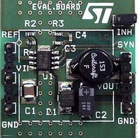
Power Management Modules & Development Tools EVAL BOARD A5973D Auto Grade
Manufacturer
STMicroelectronics
Type
DC/DC Switching Converters, Regulators & Controllersr
Datasheet
1.EVALA5973D.pdf
(30 pages)
Specifications of EVALA5973D
Input Voltage
4.4 V to 36 V
Output Voltage
1.235 V to 35 V
Board Size
23 mm x 20 mm
Product
Power Management Modules
Supply Current
2.5 A
Dimensions
23 mm x 20 mm
For Use With/related Products
AN1518
Lead Free Status / RoHS Status
Lead free / RoHS Compliant


AN1518
8
where R
If R
Equation 7
The zero of this transfer function is given by:
Equation 8
F
increase the phase margin of the loop.
The poles of the transfer function can be calculated through the following expression:
Equation 9
In the denominator of A
Equation 10
If the damping coefficient δ is very close to zero, the roots of the equation become a double
root whose value is ω
Similarly for A
Equation 11
PWM comparator
The PWM gain is given by the following formula:
Equation 12
where V
minimum value. A voltage feed forward is implemented to ensure a constant GPWM. This is
obtained by generating a sawtooth waveform directly proportional to the input voltage V
Equation 13
0
is the zero introduced by the ESR of the output capacitor and it is very important to
LOAD
OSCMAX
LOAD
>>ESR, the previous expression of A
is defined as the ratio between V
LC
is the maximum value of a sawtooth waveform and V
the poles can usually be defined as a double pole whose value is:
F PLC1 2
n
.
LC
A
,
LC
the typical second order system equation can be recognized:
s ( )
=
G
–
------------------------------------------------------------------------------------------------------------------------------------------- -
V
PWM
ESR C
=
OSCMAX
F
F
------------------------------------------------------------------------------------------------
L
O
PLC
s ( )
s
•
•
2
=
C
+
OUT
OUT
=
=
---------------------------------------------------- -
2 π
2
–
-------------------------------------------------------------
(
•
•
1
----------------------------------------------- -
2
V
V
δ
•
+
±
•
OSCMIN
OSCMAX
•
•
s
ESR C
π
LC
(
2
2
ω
ESR
ESR
•
OUT
n
+
•
1
•
can be simplified and becomes:
L
ESR C
1
L C
•
s
•
V
•
•
•
=
and I
–
C OUT
+
cc
C
C
OUT
V
ω
OUT
K V
•
OUT
2
OUT
OSCMIN
n
•
OUT
OUT
•
)
2
CC
s
–
.
4
•
)
•
s
L
+
•
1
C
OUT
OSCMIN
PWM comparator
is the
13/30
CC
.
Related parts for EVALA5973D
Image
Part Number
Description
Manufacturer
Datasheet
Request
R

Part Number:
Description:
ENERCHIP CC EVAL KIT
Manufacturer:
Cymbet Corporation
Datasheet:

Part Number:
Description:
BOARD EVAL FOR AD976
Manufacturer:
Analog Devices Inc
Datasheet:

Part Number:
Description:
BOARD EVAL FOR ADXL345
Manufacturer:
Analog Devices Inc
Datasheet:

Part Number:
Description:
ENERCHIP CC SEH EVAL KIT
Manufacturer:
Cymbet Corporation
Datasheet:

Part Number:
Description:
ENERCHIP EP ENERGY HARVEST EVAL
Manufacturer:
Cymbet Corporation
Datasheet:

Part Number:
Description:
EVAL BOARD FOR TW6864-LB2-GR
Manufacturer:
Intersil
Datasheet:
Part Number:
Description:
EVAL BOARD FOR TW8816-LB3-GR
Manufacturer:
Intersil
Datasheet:
Part Number:
Description:
EVAL BOARD FOR TW8817-TA3-GRS
Manufacturer:
Intersil
Datasheet:

Part Number:
Description:
EVALUATION MODULE FOR ADUM4160
Manufacturer:
Analog Devices Inc
Datasheet:

Part Number:
Description:
BOARD EVALUATION ADCMP581BCP
Manufacturer:
Analog Devices Inc
Datasheet:
Part Number:
Description:
BOARD EVALUATION ADM1041
Manufacturer:
Analog Devices Inc
Datasheet:

Part Number:
Description:
EVAL BOARD FOR STM32F107VCT
Manufacturer:
STMicroelectronics
Datasheet:
Part Number:
Description:
BOARD EVAL FOR AD1954
Manufacturer:
Analog Devices Inc
Datasheet:
Part Number:
Description:
BOARD EVAL FOR AD1955
Manufacturer:
Analog Devices Inc
Datasheet:

Part Number:
Description:
BOARD EVAL FOR AD7655
Manufacturer:
Analog Devices Inc
Datasheet: