1N5931BRLG ON Semiconductor, 1N5931BRLG Datasheet - Page 5
1N5931BRLG
Manufacturer Part Number
1N5931BRLG
Description
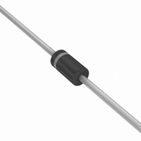
DIODE ZENER 18V 3W DO-41
Manufacturer
ON Semiconductor
Series
Surmetic™r
Datasheet
1.1N5956BRLG.pdf
(8 pages)
Specifications of 1N5931BRLG
Voltage - Zener (nom) (vz)
18V
Voltage - Forward (vf) (max) @ If
1.5V @ 200mA
Current - Reverse Leakage @ Vr
1µA @ 13.7V
Tolerance
±5%
Power - Max
3W
Impedance (max) (zzt)
12 Ohm
Mounting Type
Through Hole
Package / Case
DO-204AL, DO-41, Axial
Operating Temperature
-65°C ~ 200°C
Zener Voltage Vz Typ
18V
Power Dissipation Pd
3W
Operating Temperature Range
-65°C To +200°C
Diode Case Style
DO-41
No. Of Pins
2
Termination Type
Axial Leaded
Leakage Current Max
1µA
Rohs Compliant
Yes
Diode Type
Zener
Peak Reflow Compatible (260 C)
Yes
Zener Voltage
18 V
Voltage Tolerance
5 %
Zener Current
83 mA
Power Dissipation
3 W
Maximum Reverse Leakage Current
1 uA
Maximum Zener Impedance
12 Ohms
Maximum Operating Temperature
+ 200 C
Mounting Style
Through Hole
Minimum Operating Temperature
- 65 C
Lead Free Status / RoHS Status
Lead free / RoHS Compliant
Other names
1N5931BRLG
1N5931BRLGOSTR
1N5931BRLGOSTR
Available stocks
Company
Part Number
Manufacturer
Quantity
Price
Company:

Part Number:
1N5931BRLG
Manufacturer:
ON Semiconductor
Quantity:
20 000


APPLICATION NOTE
diode is temperature dependent, it is necessary to determine
junction temperature under any set of operating conditions
in order to calculate its value. The following procedure is
recommended:
q
P
depends on the device mounting method. q
30−40°C/W for the various clips and tie points in common
use and for printed circuit board wiring.
thermocouple placed on the lead as close as possible to the
tie point. The thermal mass connected to the tie point is
normally large enough so that it will not significantly
respond to heat surges generated in the diode as a result of
pulsed operation once steady-state conditions are achieved.
Using the measured value of T
may be determined by:
LA
D
Since the actual voltage available from a given zener
Lead Temperature, T
The temperature of the lead can also be measured using a
is the power dissipation. The value for q
is the lead-to-ambient thermal resistance (°C/W) and
T
T
L
L
J
= q
, should be determined from:
= T
LA
L
P
+ DT
D
L
, the junction temperature
+ T
JL
A
LA
LA
will vary and
is generally
1N5913B Series
http://onsemi.com
5
DT
temperature and may be found from Figure 2 for a train of
power pulses (L = 3/8 inch) or from Figure 10 for dc power.
of P
Changes in voltage, V
q
from Figures 5 and 6.
vary with time and may also be affected significantly by the
zener resistance. For best regulation, keep current
excursions as low as possible.
capability. Surge limitations are given in Figure 3. They are
lower than would be expected by considering only junction
temperature, as current crowding effects cause temperatures
to be extremely high in small spots resulting in device
degradation should the limits of Figure 3 be exceeded.
VZ
For worst-case design, using expected limits of I
Under high power-pulse operation, the zener voltage will
Data of Figure 2 should not be used to compute surge
JL
, the zener voltage temperature coefficient, is found
D
is the increase in junction temperature above the lead
and the extremes of T
DT
Z
DV = q
, can then be found from:
JL
= q
VZ
J
JL
DT
(DT
P
D
J
J
) may be estimated.
Z
, limits
Related parts for 1N5931BRLG
Image
Part Number
Description
Manufacturer
Datasheet
Request
R

Part Number:
Description:
DIODE ZENER 18V 3W DO-41
Manufacturer:
ON Semiconductor
Datasheet:

Part Number:
Description:
ON Semiconductor [VOLTAGE REGULATOR]
Manufacturer:
ON Semiconductor
Datasheet:
Part Number:
Description:
357-036-542-201 CARDEDGE 36POS DL .156 BLK LOPRO
Manufacturer:
ON Semiconductor
Datasheet:
Part Number:
Description:
357-036-542-201 CARDEDGE 36POS DL .156 BLK LOPRO
Manufacturer:
ON Semiconductor
Datasheet:
Part Number:
Description:
357-036-542-201 CARDEDGE 36POS DL .156 BLK LOPRO
Manufacturer:
ON Semiconductor
Datasheet:
Part Number:
Description:
357-036-542-201 CARDEDGE 36POS DL .156 BLK LOPRO
Manufacturer:
ON Semiconductor
Datasheet:
Part Number:
Description:
357-036-542-201 CARDEDGE 36POS DL .156 BLK LOPRO
Manufacturer:
ON Semiconductor
Datasheet:
Part Number:
Description:
357-036-542-201 CARDEDGE 36POS DL .156 BLK LOPRO
Manufacturer:
ON Semiconductor
Datasheet:
Part Number:
Description:
357-036-542-201 CARDEDGE 36POS DL .156 BLK LOPRO
Manufacturer:
ON Semiconductor
Datasheet:
Part Number:
Description:
357-036-542-201 CARDEDGE 36POS DL .156 BLK LOPRO
Manufacturer:
ON Semiconductor
Datasheet:
Part Number:
Description:
357-036-542-201 CARDEDGE 36POS DL .156 BLK LOPRO
Manufacturer:
ON Semiconductor
Datasheet:
Part Number:
Description:
357-036-542-201 CARDEDGE 36POS DL .156 BLK LOPRO
Manufacturer:
ON Semiconductor
Datasheet:
Part Number:
Description:
Manufacturer:
ON Semiconductor
Datasheet:
Part Number:
Description:
Manufacturer:
ON Semiconductor
Datasheet: