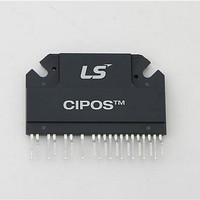
IKCS12F60AA Infineon Technologies, IKCS12F60AA Datasheet

IKCS12F60AA
Specifications of IKCS12F60AA
Available stocks
Related parts for IKCS12F60AA
IKCS12F60AA Summary of contents
Page 1
™ ...
Page 2
... Infineon Technologies AG. TrenchStop CIPOS™, CoolMOS™, CoolSET™, DuoPack™, EmCon™ and thinQ!™ are trademarks of Infineon Technologies AG. Preliminary Data Sheet CIPOS™ IKCS12F60AA 2/17 Rev.1.4 Rev. 1.4, Dec. 2007 ...
Page 3
... V+ (positive bus input voltage, Pin 10)....................................................................................................... 7 Absolute Maximum Ratings ............................................................................................................................8 Module Section ............................................................................................................................................8 IGBT and Diode Section .............................................................................................................................8 Control Section............................................................................................................................................9 Recommended Operation Conditions............................................................................................................9 Static Parameters ...........................................................................................................................................10 Dynamic Parameters ......................................................................................................................................11 Integrated Components .................................................................................................................................12 Circuit of a Typical Application.....................................................................................................................12 Test Circuits ....................................................................................................................................................14 Preliminary Data Sheet CIPOS™ IKCS12F60AA 3/17 Rev. 1.4, Dec. 2007 ...
Page 4
... Bootstrap diodes for high side supply • Integrated 100nF bootstrap capacitance • Temperature sensor, passive components for adaptions • Isolated heatsink • Creepage distance 3.1mm 4/17 CIPOS™ IKCS12F60AA compressors and washing ® ® IGBT & FW- Rev. 1.4, Dec. 2007 ...
Page 5
... Tr1, U-HS Tr3, V- Tr2, U-LS Tr4, V- RH1 RL1 RH2 RL2 CbsH1 CbsH2 VCC Driver-IC /HIN1 /HIN2 /HIN3 /LIN1 /LIN2 /LIN3 R RTS C2 5/17 CIPOS™ IKCS12F60AA Tr5, W-HS D5 Tr6, W-LS D6 RH3 RL3 CbsH3 For integrated components see Table Rev. 1.4, Dec. 2007 ...
Page 6
... IGBT The Schmitt-trigger input threshold of them are Figure 2: Input pin structure Preliminary Data Sheet CIPOS™ IKCS12F60AA Pin Description such to guarantee LSTTL and CMOS compatibility down to 3.3V controller outputs. Pull-up resistor of about 75 kOhm is internally provided to pre-bias inputs during supply start-up and a zener clamp is provided for pin protection purposes ...
Page 7
... V+ (positive bus input voltage, Pin 10) The high side IGBT are connected to the bus = 11 voltage recommended, that the bus voltage does not exceed 500 V. 7/17 CIPOS™ IKCS12F60AA high side power device = 11.9 V and a BSUV+ = 10.3 V according to ...
Page 8
... T = 80°C,T < 150°C t limited vJmax ≤ 15V,V 400V ≤ 150° 25° tot IGBT T vjI Diode T vjD 8/17 CIPOS™ IKCS12F60AA Value Min max -40 125 - 125 - 260 2500 - - 0.6 - 150 N/mm² 3 Value min max 600 - , -40 150 ...
Page 9
... V p S1,2,3 t ≥ 250ns p t < 500ns p t ≥ 500ns p LIN, HIN, EN, ITRIP J,IC f PWM -Potential unless otherwise specified. SS Symbol 9/17 CIPOS™ IKCS12F60AA Value Unit min typ max - - 3.0 K 4.2 Value Unit min max - 600 V - 550 VDD-VBS-50 - VDD-VBS 125 - 20 kHz ...
Page 10
... low float ITRIP 550V 125°C S j,IC 10/17 CIPOS™ IKCS12F60AA Value min typ max CE(sat) - 1.7 2. 1.6 2.05 - 1.6 CES - - - - 40 1000 - 35 - C(SC) 1.7 2.1 2.4 IH 0.7 0.9 1.1 IL 1.9 2.1 2.3 EN,TH+ 1.1 1.32 1.5 EN,TH- 360 450 540 ...
Page 11
... ITRIP DT PWM 6A 300V E out 25° 150° 6A 300V E out DC off T = 25° 150° 6A 300V E out DC rec T = 25° 150°C vj 11/17 CIPOS™ IKCS12F60AA Value Unit min typ max - 617 - 832 - 900 - ns - 900 - ns 155 225 380 ns 120 270 - ns - 200 - ns - 350 - ...
Page 12
... Bootstrap Capacitor Circuit of a Typical Application 1 Symbols according to Figure 1 Preliminary Data Sheet Condition Symbol Rbs 25°C RTS NTC T = 25°C B25 NTC 100mA FDbs FDbs C1 C2 CbsH x 12/17 CIPOS™ IKCS12F60AA 1 Value Unit min typ max Ω kΩ - 100 - - 4250 - K - 1.9 2. 100 ...
Page 13
... Figure 6. Typical switching times 0.15mJ 0.10mJ E off 0.05mJ E rec 0.00mJ 25°C 15A Figure 8. Typical switching energy losses = 150°C, 13/17 CIPOS™ IKCS12F60AA 50°C 75°C 100°C 125° JUNCTION TEMPERATURE vJ function of junction temperature (inductive load 300V 0/15V Dynamic test circuit in Figure A) ...
Page 14
... Single Pulse K/W 100ns 1µs 2V Figure 24. Diode transient thermal impedance as a function of pulse width (D=t 14/17 CIPOS™ IKCS12F60AA V =25°C GE 125°C 150° 15V) DD IGBT Diode 10µs 100µs 1ms 10ms 100ms PULSE WIDTH P /T) P Rev ...
Page 15
... Figure D: Switching times definition and switching energy definition Preliminary Data Sheet t Erec ∫ = ⋅ Erec Figure B: Definition of diodes switching characteristics Eoff t Eoff ∫ = ⋅ CEx Cx 0 15/17 CIPOS™ IKCS12F60AA d(on) r 90% 10 Eon t Eon ∫ = ⋅ Eon CEx Cx 0 Rev. 1.4, Dec. 2007 ...
Page 16
... LIN LO Figure E: Short Pulse suppression Preliminary Data Sheet t FILIN HIN on off LIN high HO LO 16/17 CIPOS™ IKCS12F60AA t FILIN on off low Rev. 1.4, Dec. 2007 ...
Page 17
... Package Outline IKCS12F60AA Description Weight Preliminary Data Sheet CIPOS™ IKCS12F60AA Condition Symbol min m P 17/17 Value Unit typ max - Rev. 1.4, Dec. 2007 ...


