EVAL-ADAU1761Z Analog Devices Inc, EVAL-ADAU1761Z Datasheet - Page 50
EVAL-ADAU1761Z
Manufacturer Part Number
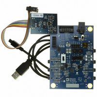
EVAL-ADAU1761Z
Description
Eval Board For ADAU1761
Manufacturer
Analog Devices Inc
Series
SigmaDSP®r
Specifications of EVAL-ADAU1761Z
Main Purpose
Audio, CODEC
Embedded
Yes, DSP
Utilized Ic / Part
ADAU1761
Primary Attributes
Stereo, 24-Bit, 8 ~ 96 kHz Sampling Rate, GUI Tool
Secondary Attributes
I²C and GPIO Interfaces, 2 Differential and 1 Stereo Single-Ended Analog Inputs and Outputs
Silicon Manufacturer
Analog Devices
Core Architecture
SigmaDSP
Silicon Core Number
ADAU1761
Silicon Family Name
SigmaDSP
Application Sub Type
Audio
Lead Free Status / RoHS Status
Lead free / RoHS Compliant
Available stocks
Company
Part Number
Manufacturer
Quantity
Price
Company:

Part Number:
EVAL-ADAU1761Z
Manufacturer:
Analog Devices Inc
Quantity:
135


ADAU1761
GENERAL-PURPOSE INPUT/OUTPUT
The serial data input/output pins (Pin 26 to Pin 29) are shared
with the general-purpose input/output function. Each of these
four pins can be set to only one of these functions. The function
of these pins is set in the serial data/GPIO pin configuration
register (Register R60, Address 0x40F4).
The GPIOx pins can be used as inputs or outputs. These pins
are readable and can be set through the control port or directly
by the SigmaDSP core. When configured as inputs, the GPIOx
pins can be used with push-button switches or rotary encoders
to control DSP program settings. These pins can also be used
with digital outputs to drive LEDs or external logic to indicate
the status of internal signals and control other devices. Examples
of this use include indicating signal overload, signal present,
and button press confirmation.
When configured as an output, each GPIO pin can typically
drive 2 mA, which is enough current to directly drive some
high efficiency LEDs. Standard LEDs require about 20 mA of
current and can be driven from a GPIO output with an external
transistor or buffer. Because of problems that can arise from
simultaneously driving or sinking a large amount of current on
many pins, avoid connecting high efficiency LEDs directly to
many or all of the GPIO pins when designing the application.
Rev. C | Page 50 of 92
If many LEDs are required, use an external driver. When the
GPIO pins are configured as open-collector outputs, they
should be pulled up to a maximum voltage equal to the voltage
set on IOVDD.
The configuration of the GPIO functions is set up in the
GPIO pin control registers (Register R48 to Register R51,
Address 0x40C6 to Address 0x40C9).
GPIO PINS SET FROM THE CONTROL PORT
The GPIO pins can also be configured to be directly controlled
from the I
mode, four memory locations are enabled for the GPIO pin
settings. The physical settings on the GPIO pins mirror the
settings of the LSB of these 4-byte-wide memory locations.
Table 32. GPIOx Pin Memory Settings (Set from Control Port)
Decimal
1568
1569
1570
1571
Memory Location
2
C/SPI control port. When the pins are set to this
Hex
0x0620
0x0621
0x0622
0x0623
Bits[31:1]
Reserved
Reserved
Reserved
Reserved
Bit 0
GPIO0SET
GPIO1SET
GPIO2SET
GPIO3SET
Related parts for EVAL-ADAU1761Z
Image
Part Number
Description
Manufacturer
Datasheet
Request
R


Part Number:
Description:
BOARD EVAL FOR SI270X-A
Manufacturer:
Silicon Laboratories Inc
Datasheet:

Part Number:
Description:
BUCK CONV REF DESIGN KIT IP1201
Manufacturer:
International Rectifier
Datasheet:
Part Number:
Description:
BOARD DEMO SYNC DUAL BUCK CNVTER
Manufacturer:
International Rectifier
Datasheet:
Part Number:
Description:
BOARD DEMO SYNC BUCK CONVETER
Manufacturer:
International Rectifier
Datasheet:

Part Number:
Description:
EVALBOARD/EB Omnidirectional microphone - Analog
Manufacturer:
Analog Devices
Datasheet:
Part Number:
Description:
EVALBOARD/EB Omnidirectional microphone - Analog
Manufacturer:
Analog Devices
Datasheet:


Part Number:
Description:
BOARD EVAL LED DRIVER LT3756
Manufacturer:
Linear Technology
Datasheet:

Part Number:
Description:
BOARD EVAL FOR AD7741/7742
Manufacturer:
Analog Devices Inc
Datasheet:

Part Number:
Description:
±1.7g Dual-Axis IMEMS Accelerometer Evaluation Board
Manufacturer:
Analog Devices Inc
Datasheet:

Part Number:
Description:
IC MULTIPLIER ANALOG 8-SOIC T/R
Manufacturer:
Analog Devices Inc
Datasheet:

Part Number:
Description:
IC ANALOG MULTIPLIER 8-DIP
Manufacturer:
Analog Devices Inc
Datasheet:
Part Number:
Description:
IC ANALOG MULTIPLIER 8-SOIC
Manufacturer:
Analog Devices Inc
Datasheet:
Part Number:
Description:
IC ANALOG MULTIPLIER 8-DIP
Manufacturer:
Analog Devices Inc
Datasheet: