EVAL-ADAU1761Z Analog Devices Inc, EVAL-ADAU1761Z Datasheet - Page 58
EVAL-ADAU1761Z
Manufacturer Part Number
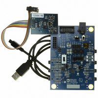
EVAL-ADAU1761Z
Description
Eval Board For ADAU1761
Manufacturer
Analog Devices Inc
Series
SigmaDSP®r
Specifications of EVAL-ADAU1761Z
Main Purpose
Audio, CODEC
Embedded
Yes, DSP
Utilized Ic / Part
ADAU1761
Primary Attributes
Stereo, 24-Bit, 8 ~ 96 kHz Sampling Rate, GUI Tool
Secondary Attributes
I²C and GPIO Interfaces, 2 Differential and 1 Stereo Single-Ended Analog Inputs and Outputs
Silicon Manufacturer
Analog Devices
Core Architecture
SigmaDSP
Silicon Core Number
ADAU1761
Silicon Family Name
SigmaDSP
Application Sub Type
Audio
Lead Free Status / RoHS Status
Lead free / RoHS Compliant
Available stocks
Company
Part Number
Manufacturer
Quantity
Price
Company:

Part Number:
EVAL-ADAU1761Z
Manufacturer:
Analog Devices Inc
Quantity:
135


ADAU1761
R7: Record Mixer Right (Mixer 2) Control 1, 16,397 (0x400D)
This register controls the gain boost of the right channel differential PGA input and the gain for the right channel auxiliary input in the
record path. The right channel record mixer is referred to as Mixer 2.
Bit 7
Table 41. Record Mixer Right (Mixer 2) Control 1 Register
Bits
[4:3]
[2:0]
R8: Left Differential Input Volume Control, 16,398 (0x400E)
This register enables the differential path and sets the volume control for the left differential PGA input.
Bit 7
Table 42. Left Differential Input Volume Control Register
Bits
[7:2]
1
0
Bit Name
RDBOOST[1:0]
MX2AUXG[2:0]
Bit Name
LDVOL[5:0]
LDMUTE
LDEN
Bit 6
Bit 6
Reserved
Description
Right channel differential PGA input gain boost, input to Mixer 2. The right differential input uses the RINP
(positive signal) and RINN (negative signal) pins.
Setting
00
01
10
11
Right single-ended auxiliary input gain from the RAUX pin in the record path, input to Mixer 2.
Setting
000
001
010
011
100
101
110
111
Description
Left channel differential PGA input volume control. The left differential input uses the LINP (positive signal) and
LINN (negative signal) pins. Each step corresponds to a 0.75 dB increase in gain. See Table 92 for a complete list
of the volume settings.
Setting
000000
000001
…
010000
…
111110
111111
Left differential input mute control.
0 = mute (default).
1 = unmute.
Left differential PGA enable. When enabled, the LINP and LINN pins are used as a full differential pair. When
disabled, these two pins are configured as two single-ended inputs with the signals routed around the PGA.
0 = disabled (default).
1 = enabled.
Bit 5
Bit 5
LDVOL[5:0]
Bit 4
Bit 4
Gain Boost
Mute (default)
0 dB
20 dB
Reserved
Auxiliary Input Gain
Mute (default)
−12 dB
−9 dB
−6 dB
−3 dB
0 dB
3 dB
6 dB
Volume
−12 dB (default)
−11.25 dB
…
0 dB
…
34.5 dB
35.25 dB
Rev. C | Page 58 of 92
RDBOOST[1:0]
Bit 3
Bit 3
Bit 2
Bit 2
Bit 1
Bit 1
LDMUTE
MX2AUXG[2:0]
Bit 0
Bit 0
LDEN
Related parts for EVAL-ADAU1761Z
Image
Part Number
Description
Manufacturer
Datasheet
Request
R


Part Number:
Description:
BOARD EVAL FOR SI270X-A
Manufacturer:
Silicon Laboratories Inc
Datasheet:

Part Number:
Description:
BUCK CONV REF DESIGN KIT IP1201
Manufacturer:
International Rectifier
Datasheet:
Part Number:
Description:
BOARD DEMO SYNC DUAL BUCK CNVTER
Manufacturer:
International Rectifier
Datasheet:
Part Number:
Description:
BOARD DEMO SYNC BUCK CONVETER
Manufacturer:
International Rectifier
Datasheet:

Part Number:
Description:
EVALBOARD/EB Omnidirectional microphone - Analog
Manufacturer:
Analog Devices
Datasheet:
Part Number:
Description:
EVALBOARD/EB Omnidirectional microphone - Analog
Manufacturer:
Analog Devices
Datasheet:


Part Number:
Description:
BOARD EVAL LED DRIVER LT3756
Manufacturer:
Linear Technology
Datasheet:

Part Number:
Description:
BOARD EVAL FOR AD7741/7742
Manufacturer:
Analog Devices Inc
Datasheet:

Part Number:
Description:
±1.7g Dual-Axis IMEMS Accelerometer Evaluation Board
Manufacturer:
Analog Devices Inc
Datasheet:

Part Number:
Description:
IC MULTIPLIER ANALOG 8-SOIC T/R
Manufacturer:
Analog Devices Inc
Datasheet:

Part Number:
Description:
IC ANALOG MULTIPLIER 8-DIP
Manufacturer:
Analog Devices Inc
Datasheet:
Part Number:
Description:
IC ANALOG MULTIPLIER 8-SOIC
Manufacturer:
Analog Devices Inc
Datasheet:
Part Number:
Description:
IC ANALOG MULTIPLIER 8-DIP
Manufacturer:
Analog Devices Inc
Datasheet: