EVAL-ADAU1761Z Analog Devices Inc, EVAL-ADAU1761Z Datasheet - Page 59
EVAL-ADAU1761Z
Manufacturer Part Number
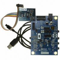
EVAL-ADAU1761Z
Description
Eval Board For ADAU1761
Manufacturer
Analog Devices Inc
Series
SigmaDSP®r
Specifications of EVAL-ADAU1761Z
Main Purpose
Audio, CODEC
Embedded
Yes, DSP
Utilized Ic / Part
ADAU1761
Primary Attributes
Stereo, 24-Bit, 8 ~ 96 kHz Sampling Rate, GUI Tool
Secondary Attributes
I²C and GPIO Interfaces, 2 Differential and 1 Stereo Single-Ended Analog Inputs and Outputs
Silicon Manufacturer
Analog Devices
Core Architecture
SigmaDSP
Silicon Core Number
ADAU1761
Silicon Family Name
SigmaDSP
Application Sub Type
Audio
Lead Free Status / RoHS Status
Lead free / RoHS Compliant
Available stocks
Company
Part Number
Manufacturer
Quantity
Price
Company:

Part Number:
EVAL-ADAU1761Z
Manufacturer:
Analog Devices Inc
Quantity:
135


R9: Right Differential Input Volume Control, 16,399 (0x400F)
This register enables the differential path and sets the volume control for the right differential PGA input.
Bit 7
Table 43. Right Differential Input Volume Control Register
Bits
[7:2]
1
0
R10: Record Microphone Bias Control, 16,400 (0x4010)
This register controls the MICBIAS pin settings for biasing electret type analog microphones.
Bit 7
Table 44. Record Microphone Bias Control Register
Bits
3
2
0
Bit Name
MPERF
MBI
MBIEN
Bit Name
RDVOL[5:0]
RDMUTE
RDEN
Bit 6
Bit 6
Right differential input mute control.
Description
Microphone bias is enabled for high performance or normal operation. High performance operation sources
more current to the microphone.
0 = normal operation (default).
1 = high performance.
Microphone voltage bias as a fraction of AVDD.
0 = 0.90 × AVDD (default).
1 = 0.65 × AVDD.
Enables the MICBIAS output.
0 = disabled (default).
1 = enabled.
Description
Right channel differential PGA input volume control. The right differential input uses the RINP (positive signal)
and RINN (negative signal) pins. Each step corresponds to a 0.75 dB increase in gain. See Table 92 for a complete
list of the volume settings.
Setting
000000
000001
…
010000
…
111110
111111
0 = mute (default).
1 = unmute.
Right differential PGA enable. When enabled, the RINP and RINN pins are used as a full differential pair. When
disabled, these two pins are configured as two single-ended inputs with the signals routed around the PGA.
0 = disabled (default).
1 = enabled.
Reserved
Bit 5
Bit 5
RDVOL[5:0]
Bit 4
Bit 4
Volume
−12 dB (default)
−11.25 dB
…
0 dB
…
34.5 dB
35.25 dB
Rev. C | Page 59 of 92
Bit 3
Bit 3
MPERF
Bit 2
Bit 2
MBI
Bit 1
RDMUTE
Bit 1
Reserved
ADAU1761
Bit 0
RDEN
Bit 0
MBIEN
Related parts for EVAL-ADAU1761Z
Image
Part Number
Description
Manufacturer
Datasheet
Request
R


Part Number:
Description:
BOARD EVAL FOR SI270X-A
Manufacturer:
Silicon Laboratories Inc
Datasheet:

Part Number:
Description:
BUCK CONV REF DESIGN KIT IP1201
Manufacturer:
International Rectifier
Datasheet:
Part Number:
Description:
BOARD DEMO SYNC DUAL BUCK CNVTER
Manufacturer:
International Rectifier
Datasheet:
Part Number:
Description:
BOARD DEMO SYNC BUCK CONVETER
Manufacturer:
International Rectifier
Datasheet:

Part Number:
Description:
EVALBOARD/EB Omnidirectional microphone - Analog
Manufacturer:
Analog Devices
Datasheet:
Part Number:
Description:
EVALBOARD/EB Omnidirectional microphone - Analog
Manufacturer:
Analog Devices
Datasheet:


Part Number:
Description:
BOARD EVAL LED DRIVER LT3756
Manufacturer:
Linear Technology
Datasheet:

Part Number:
Description:
BOARD EVAL FOR AD7741/7742
Manufacturer:
Analog Devices Inc
Datasheet:

Part Number:
Description:
±1.7g Dual-Axis IMEMS Accelerometer Evaluation Board
Manufacturer:
Analog Devices Inc
Datasheet:

Part Number:
Description:
IC MULTIPLIER ANALOG 8-SOIC T/R
Manufacturer:
Analog Devices Inc
Datasheet:

Part Number:
Description:
IC ANALOG MULTIPLIER 8-DIP
Manufacturer:
Analog Devices Inc
Datasheet:
Part Number:
Description:
IC ANALOG MULTIPLIER 8-SOIC
Manufacturer:
Analog Devices Inc
Datasheet:
Part Number:
Description:
IC ANALOG MULTIPLIER 8-DIP
Manufacturer:
Analog Devices Inc
Datasheet: