EVAL-ADT7X10EBZ Analog Devices Inc, EVAL-ADT7X10EBZ Datasheet - Page 5
EVAL-ADT7X10EBZ
Manufacturer Part Number
EVAL-ADT7X10EBZ
Description
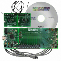
Evaluation Board I.c.
Manufacturer
Analog Devices Inc
Specifications of EVAL-ADT7X10EBZ
Sensor Type
Temperature
Sensing Range
-55°C ~ 150°C
Interface
I²C
Sensitivity
±0.5°C
Voltage - Supply
2.7 V ~ 5.5 V
Embedded
No
Utilized Ic / Part
ADT7410
Silicon Manufacturer
Analog Devices
Silicon Core Number
ADT7410
Kit Application Type
Sensing - Temperature
Application Sub Type
Temperature Sensor
Lead Free Status / RoHS Status
Lead free / RoHS Compliant
Other names
EVAL-ADT7410EBZ
EVAL-ADT7410EBZ
EVAL-ADT7410EBZ


ABSOLUTE MAXIMUM RATINGS
Table 3.
Parameter
V
SDA Voltage to GND
SCL Output Voltage to GND
A0 Input Voltage to GND
A1 Input Voltage to GND
CT and INT Output Voltage to GND
ESD Rating (Human Body Model)
Operating Temperature Range
Storage Temperature Range
Maximum Junction Temperature, T
8-Lead SOIC-N (R-8)
Thermal Impedance
IR Reflow Soldering
1
2
3
Values relate to package being used on a standard 2-layer PCB. This gives a
worst-case θ
vs. ambient temperature (T
T
Junction-to-case resistance is applicable to components featuring a
preferential flow direction, for example, components mounted on a heat
sink. Junction-to-ambient is more useful for air-cooled, PCB-mounted
components.
DD
Time at Peak Temperature
Ramp-Up Rate
Ramp-Down Rate
Time from 25°C to Peak Temperature
A
Power Dissipation
θ
θ
Peak Temperature (RoHS-Compliant
= ambient temperature.
JA
JC
to GND
Package)
, Junction-to-Ambient (Still Air)
, Junction-to-Case
JA
and θ
JC
. See Figure 3 for a plot of maximum power dissipation
3
1
A
).
JMAX
Rating
−0.3 V to +7 V
−0.3 V to V
−0.3 V to V
−0.3 V to V
−0.3 V to V
−0.3 V to V
2.0 kV
−55°C to +150°C
−65°C to +160°C
150°C
W
121°C/W
56°C/W
220°C
260°C (0°C)
20 sec to 40 sec
3°C/sec maximum
−6°C/sec maximum
8 minutes maximum
MAX
= (T
JMAX
DD
DD
DD
DD
DD
+ 0.3 V
+ 0.3 V
+ 0.3 V
+ 0.3 V
+ 0.3 V
− T
A
2
)/θ
Rev. 0 | Page 5 of 24
JA
Stresses above those listed under Absolute Maximum Ratings
may cause permanent damage to the device. This is a stress
rating only; functional operation of the device at these or any
other conditions above those indicated in the operational
section of this specification is not implied. Exposure to absolute
maximum rating conditions for extended periods may affect
device reliability.
ESD CAUTION
Figure 3. SOIC_N Maximum Power Dissipation vs. Temperature
1.2
1.0
0.8
0.6
0.4
0.2
0
TEMPERATURE (°C)
MAX PD = 3.4mW AT 150°C
ADT7410
Related parts for EVAL-ADT7X10EBZ
Image
Part Number
Description
Manufacturer
Datasheet
Request
R


Part Number:
Description:
BOARD EVAL FOR SI270X-A
Manufacturer:
Silicon Laboratories Inc
Datasheet:

Part Number:
Description:
BUCK CONV REF DESIGN KIT IP1201
Manufacturer:
International Rectifier
Datasheet:
Part Number:
Description:
BOARD DEMO SYNC DUAL BUCK CNVTER
Manufacturer:
International Rectifier
Datasheet:
Part Number:
Description:
BOARD DEMO SYNC BUCK CONVETER
Manufacturer:
International Rectifier
Datasheet:

Part Number:
Description:
EVALBOARD/EB Omnidirectional microphone - Analog
Manufacturer:
Analog Devices
Datasheet:
Part Number:
Description:
EVALBOARD/EB Omnidirectional microphone - Analog
Manufacturer:
Analog Devices
Datasheet:


Part Number:
Description:
BOARD EVAL LED DRIVER LT3756
Manufacturer:
Linear Technology
Datasheet:

Part Number:
Description:
BOARD EVAL FOR AD7741/7742
Manufacturer:
Analog Devices Inc
Datasheet:

Part Number:
Description:
±1.7g Dual-Axis IMEMS Accelerometer Evaluation Board
Manufacturer:
Analog Devices Inc
Datasheet:

Part Number:
Description:
IC MULTIPLIER ANALOG 8-SOIC T/R
Manufacturer:
Analog Devices Inc
Datasheet:

Part Number:
Description:
IC ANALOG MULTIPLIER 8-DIP
Manufacturer:
Analog Devices Inc
Datasheet:
Part Number:
Description:
IC ANALOG MULTIPLIER 8-SOIC
Manufacturer:
Analog Devices Inc
Datasheet:
Part Number:
Description:
IC ANALOG MULTIPLIER 8-DIP
Manufacturer:
Analog Devices Inc
Datasheet: