SI270X-A-EVB Silicon Laboratories Inc, SI270X-A-EVB Datasheet - Page 20
SI270X-A-EVB
Manufacturer Part Number
SI270X-A-EVB
Description
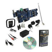
BOARD EVAL FOR SI270X-A
Manufacturer
Silicon Laboratories Inc
Datasheet
1.SI2704-A10-GM.pdf
(46 pages)
Specifications of SI270X-A-EVB
Board Type
Fully Populated
Amplifier Type
Class D
Output Type
2-Channel (Stereo) with Stereo Headphones
Max Output Power X Channels @ Load
5W x 2 @ 3 Ohm
Voltage - Supply
9V
Utilized Ic / Part
SI270X-A
Description/function
Audio Amplifiers
Output Power
5 W
Product
Audio Modules
For Use With/related Products
Si270x
Lead Free Status / RoHS Status
Lead free / RoHS Compliant
Operating Temperature
-
Lead Free Status / Rohs Status
Lead free / RoHS Compliant
Other names
336-1929


Si2704/05/06/07-A10
4.2.2. Standby Mode
Standby Mode is a reduced power state where the register states are preserved and the 2-Wire interface is fully
operational, allowing for new parameters and configuration settings to be programmed even though the amplifier
output is powered down. This state has the shortest wake-up time relative to the other low power modes. If the
buffered reference clock output (CLKO) is enabled, the timing generation circuitry remains active.
Standby Mode is initiated by setting the STANDBY argument of the ACTIVATE command via the 2-Wire interface.
Standby Mode can also be initiated by setting the AAD argument of the ACTIVATE command, which additionally
enables the Audio Activity Detector. See "4.5.2. Audio Activity Detector" on page 24 for additional information
about this setting.
To avoid clicks and pops in the audio output, mute is first asserted before entering Standby Mode.
4.2.3. Sleep Mode
Sleep Mode is the lowest power consumption state in which the chip parameters and configurations are retained.
However, chip parameter and configuration settings cannot be programmed and the buffered reference clock
output (CLKO) is disabled in this mode. The time to activate the chip is shorter from the Sleep Mode than when
activating from the Power Down Mode.
Sleep mode is initiated by setting the SLEEP argument of the ACTIVATE command.
4.2.4. Power Down Mode and Reset
Asserting the RST pin low disables the analog and digital circuitry, resets the registers to their default settings, and
disables the 2-Wire bus. The RST pin should always be asserted low when power to the device is ramped up, and
released once the power supply voltages have stabilized.
After RST is released high, the chip comes up in Power Down Mode with the registers set to their default values.
The 2-Wire interface remains active but only responds to the POWER_UP command that puts the device into
20
Sleep
Mode
POWER_DOWN
[ SLEEP / STANDBY ]
ACTIVATE
Figure 14. Operating Modes
POWER_DOWN
RESET
Assert
Power Down
[ SLEEP / ACTIVE ]
Rev. 0.6
Standby
RESET
ACTIVATE
Mode
Mode
POWER_UP
Release
RESET
[ ACTIVE / STANDBY / AAD ]
ACTIVATE
POWER_DOWN
Active
Mode
Related parts for SI270X-A-EVB
Image
Part Number
Description
Manufacturer
Datasheet
Request
R

Part Number:
Description:
SMD/C°/SINGLE-ENDED OUTPUT SILICON OSCILLATOR
Manufacturer:
Silicon Laboratories Inc
Part Number:
Description:
Manufacturer:
Silicon Laboratories Inc
Datasheet:
Part Number:
Description:
N/A N/A/SI4010 AES KEYFOB DEMO WITH LCD RX
Manufacturer:
Silicon Laboratories Inc
Datasheet:
Part Number:
Description:
N/A N/A/SI4010 SIMPLIFIED KEY FOB DEMO WITH LED RX
Manufacturer:
Silicon Laboratories Inc
Datasheet:
Part Number:
Description:
N/A/-40 TO 85 OC/EZLINK MODULE; F930/4432 HIGH BAND (REV E/B1)
Manufacturer:
Silicon Laboratories Inc
Part Number:
Description:
EZLink Module; F930/4432 Low Band (rev e/B1)
Manufacturer:
Silicon Laboratories Inc
Part Number:
Description:
I°/4460 10 DBM RADIO TEST CARD 434 MHZ
Manufacturer:
Silicon Laboratories Inc
Part Number:
Description:
I°/4461 14 DBM RADIO TEST CARD 868 MHZ
Manufacturer:
Silicon Laboratories Inc
Part Number:
Description:
I°/4463 20 DBM RFSWITCH RADIO TEST CARD 460 MHZ
Manufacturer:
Silicon Laboratories Inc
Part Number:
Description:
I°/4463 20 DBM RADIO TEST CARD 868 MHZ
Manufacturer:
Silicon Laboratories Inc
Part Number:
Description:
I°/4463 27 DBM RADIO TEST CARD 868 MHZ
Manufacturer:
Silicon Laboratories Inc
Part Number:
Description:
I°/4463 SKYWORKS 30 DBM RADIO TEST CARD 915 MHZ
Manufacturer:
Silicon Laboratories Inc
Part Number:
Description:
N/A N/A/-40 TO 85 OC/4463 RFMD 30 DBM RADIO TEST CARD 915 MHZ
Manufacturer:
Silicon Laboratories Inc
Part Number:
Description:
I°/4463 20 DBM RADIO TEST CARD 169 MHZ
Manufacturer:
Silicon Laboratories Inc