SI270X-A-EVB Silicon Laboratories Inc, SI270X-A-EVB Datasheet - Page 21
SI270X-A-EVB
Manufacturer Part Number
SI270X-A-EVB
Description
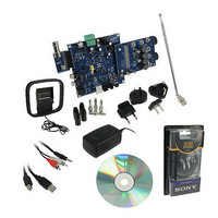
BOARD EVAL FOR SI270X-A
Manufacturer
Silicon Laboratories Inc
Datasheet
1.SI2704-A10-GM.pdf
(46 pages)
Specifications of SI270X-A-EVB
Board Type
Fully Populated
Amplifier Type
Class D
Output Type
2-Channel (Stereo) with Stereo Headphones
Max Output Power X Channels @ Load
5W x 2 @ 3 Ohm
Voltage - Supply
9V
Utilized Ic / Part
SI270X-A
Description/function
Audio Amplifiers
Output Power
5 W
Product
Audio Modules
For Use With/related Products
Si270x
Lead Free Status / RoHS Status
Lead free / RoHS Compliant
Operating Temperature
-
Lead Free Status / Rohs Status
Lead free / RoHS Compliant
Other names
336-1929


Standby Mode so that the high power outputs are prevented from being enabled prior to the registers being
configured. Any other command sent to the device is acknowledged on the bus but ignored by the device. This
mode has the highest wake-up time and lowest power consumption of the three low power modes.
A POWER_DOWN command causes a transition to Power Down Mode, disabling the outputs and resetting all
parameter registers to default values.
4.3. Chip Configuration
The Si270x can be programmed via the 2-Wire interface for several operating configurations.
4.3.1. Multi-Function Pins (MFPs)
Three multi-function pins (MFPs) support a wide range of system configurations while minimizing pin count. These
MFPs are programmed via the 2-Wire interface. Table 13 outlines all available signals, and Table 14 shows the
signal configuration options available on each MFP with the default in bold.
The MFPs default to High-Z state. MFP1 can be programmed to be signal INT or GPO1. MFP2 can be
programmed to be signal OUTSEL, DIN2, DOUT2 or GPO2. MFP3 can be programmed to be signal DIN3, DOUT
or GPO3. Table 14 summarizes the MFP configuration options with the default functionality shown in bold.
The Si270x can receive digital I
being only one input. For cases where more than one signal input is desired or alternatively a signal output is
desired, the MFPs should be programmed to an appropriate configuration with additional DINx/DOUT signals.
Three general purpose output (GPO) pins are also available. The GPOs can be programmed to output logic 1,
logic 0, or a Hi-Z state. These pins can be used for example to control multiplexer switches in the application via
the 2-Wire bus.
MFP pin function is established using the MFP_PIN_CFG command. Refer to the “AN469: Si270x Programming
Guide” for more information on the options and settings requested for operation of the multi function pins.
Pin Name
MFP1
MFP2
MFP3
Table 13. Multi-Function Signal Definitions
2
S audio signal from up to three different sources with the default configuration
Table 14. MFP Configuration Options
Signal Name
OUTSEL
GPO1–3
#13 (eTQFP)
#14 (eTQFP)
#10 (eTQFP)
Pin Number
DOUT
#10 (QFN)
#11 (QFN)
DIN2
DIN3
#7 (QFN)
INT
Tri-level output mode select
Functional Description
Rev. 0.6
General purpose output
High-Z, OUTSEL, DIN2, DOUT, GPO2
I
I
I
2
2
2
Interrupt flag
S data input 2
S data input 3
High-Z, DIN3, DOUT, GPO3
S data output
High-Z, INT, GPO1
Signal Options
Si2704/05/06/07-A10
21
Related parts for SI270X-A-EVB
Image
Part Number
Description
Manufacturer
Datasheet
Request
R

Part Number:
Description:
SMD/C°/SINGLE-ENDED OUTPUT SILICON OSCILLATOR
Manufacturer:
Silicon Laboratories Inc
Part Number:
Description:
Manufacturer:
Silicon Laboratories Inc
Datasheet:
Part Number:
Description:
N/A N/A/SI4010 AES KEYFOB DEMO WITH LCD RX
Manufacturer:
Silicon Laboratories Inc
Datasheet:
Part Number:
Description:
N/A N/A/SI4010 SIMPLIFIED KEY FOB DEMO WITH LED RX
Manufacturer:
Silicon Laboratories Inc
Datasheet:
Part Number:
Description:
N/A/-40 TO 85 OC/EZLINK MODULE; F930/4432 HIGH BAND (REV E/B1)
Manufacturer:
Silicon Laboratories Inc
Part Number:
Description:
EZLink Module; F930/4432 Low Band (rev e/B1)
Manufacturer:
Silicon Laboratories Inc
Part Number:
Description:
I°/4460 10 DBM RADIO TEST CARD 434 MHZ
Manufacturer:
Silicon Laboratories Inc
Part Number:
Description:
I°/4461 14 DBM RADIO TEST CARD 868 MHZ
Manufacturer:
Silicon Laboratories Inc
Part Number:
Description:
I°/4463 20 DBM RFSWITCH RADIO TEST CARD 460 MHZ
Manufacturer:
Silicon Laboratories Inc
Part Number:
Description:
I°/4463 20 DBM RADIO TEST CARD 868 MHZ
Manufacturer:
Silicon Laboratories Inc
Part Number:
Description:
I°/4463 27 DBM RADIO TEST CARD 868 MHZ
Manufacturer:
Silicon Laboratories Inc
Part Number:
Description:
I°/4463 SKYWORKS 30 DBM RADIO TEST CARD 915 MHZ
Manufacturer:
Silicon Laboratories Inc
Part Number:
Description:
N/A N/A/-40 TO 85 OC/4463 RFMD 30 DBM RADIO TEST CARD 915 MHZ
Manufacturer:
Silicon Laboratories Inc
Part Number:
Description:
I°/4463 20 DBM RADIO TEST CARD 169 MHZ
Manufacturer:
Silicon Laboratories Inc