SI270X-A-EVB Silicon Laboratories Inc, SI270X-A-EVB Datasheet - Page 24
SI270X-A-EVB
Manufacturer Part Number
SI270X-A-EVB
Description
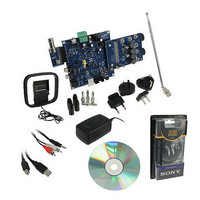
BOARD EVAL FOR SI270X-A
Manufacturer
Silicon Laboratories Inc
Datasheet
1.SI2704-A10-GM.pdf
(46 pages)
Specifications of SI270X-A-EVB
Board Type
Fully Populated
Amplifier Type
Class D
Output Type
2-Channel (Stereo) with Stereo Headphones
Max Output Power X Channels @ Load
5W x 2 @ 3 Ohm
Voltage - Supply
9V
Utilized Ic / Part
SI270X-A
Description/function
Audio Amplifiers
Output Power
5 W
Product
Audio Modules
For Use With/related Products
Si270x
Lead Free Status / RoHS Status
Lead free / RoHS Compliant
Operating Temperature
-
Lead Free Status / Rohs Status
Lead free / RoHS Compliant
Other names
336-1929


Si2704/05/06/07-A10
2
4.5. Digital Audio I
S Interface
2
2
The Si270x receives digital audio data using its I
S interface. I
S inputs DIN2 and DIN3 can be configured as either
an input or output while DIN is restricted to input only, and all three can be configured to operate in either master or
slave mode. Only one output is supported at a time. All data ports operate synchronously from a single bit-clock
and frame-clock signal. During normal operation, the crossbar mixer outputs are independently programmed to be
a linear combination of any of the channels from the configured inputs with a scaling range from –1 to +1 for each
channel with 8-bit precision.
4.5.1. Auto-Rate Detection
2
The Si270x features an auto-rate detector. It actively monitors the I
S bit and frame clock inputs during operation,
detects rate changes, and makes the necessary adjustments to various clock system parameters to ensure correct
operation of the amplifier.
4.5.2. Audio Activity Detector
The device has an audio activity detector (AAD) that monitors the presence of audio at the input. In normal
operation, if the input audio level falls below a programmable threshold for a programmable period of time, it
causes the device to enter the low power Standby Mode. When the input audio level subsequently increases above
the threshold, the device returns to normal Active Mode.
4.5.3. Digital Audio Output
2
2
The Si270x provides a bypass mode that routes I
S audio input directly to the I
S output port. The output port in
turn can be connected to an off-chip device such as a DAC, DSP or digital media controller.
4.5.4. Audio data formats
2
The digital audio interface supports 3 different audio data formats: I
S, Left-Justified and DSP Mode.
2
In I
S mode, the MSB is captured on the second rising edge of DCLK following each DFS transition. The remaining
bits of the word are sent in order, down to the LSB. The left channel is transferred first when the DFS is low, and the
2
right channel is transferred when the DFS is high. Figure 17 shows a diagram for the I
S digital audio format.
In Left-Justified mode, the MSB is captured on the first rising edge of DCLK following each DFS transition. The
remaining bits of the word are sent in order, down to the LSB. The left channel is transferred first when the DFS is
high, and the right channel is transferred when the DFS is low. Figure 18 shows a diagram for the Left-Justified
digital audio format.
In DSP mode, the DFS becomes a pulse, one DCLK period wide. The left channel is transferred first, followed
immediately by the right channel. There are two options in transferring the digital audio data in DSP mode: the
MSB of the left channel can be transferred on the first rising edge of DCLK following the DFS pulse or on the
second rising edge. Figure 19 shows a diagram for the DSP digital audio format.
In all audio formats, depending on the word size, DCLK frequency and sample rates, there may be unused DCLK
cycles after the LSB of each word before the next DFS transition and MSB of the next word. In this event, for power
2
saving, in I
S slave mode DCLK sent to the Si270x can be programmed to remain low until the next DFS transition
appears.
The device supports both rising edge and falling edge DCLK. The number of audio bits in each audio sample
defaults to 24 bits and can be configured to 16, 20, 24 or 32 bits. The leading edge and the data format are
selected using the DIGITAL_AUDIO_CONFIG property.
2
4.5.5. I
S Master Mode
2
In master mode, the Si270x is configured for 32-bit word per audio sample, rising edge DCLK, and I
S mode data
format.
24
Rev. 0.6
Related parts for SI270X-A-EVB
Image
Part Number
Description
Manufacturer
Datasheet
Request
R

Part Number:
Description:
SMD/C°/SINGLE-ENDED OUTPUT SILICON OSCILLATOR
Manufacturer:
Silicon Laboratories Inc
Part Number:
Description:
Manufacturer:
Silicon Laboratories Inc
Datasheet:
Part Number:
Description:
N/A N/A/SI4010 AES KEYFOB DEMO WITH LCD RX
Manufacturer:
Silicon Laboratories Inc
Datasheet:
Part Number:
Description:
N/A N/A/SI4010 SIMPLIFIED KEY FOB DEMO WITH LED RX
Manufacturer:
Silicon Laboratories Inc
Datasheet:
Part Number:
Description:
N/A/-40 TO 85 OC/EZLINK MODULE; F930/4432 HIGH BAND (REV E/B1)
Manufacturer:
Silicon Laboratories Inc
Part Number:
Description:
EZLink Module; F930/4432 Low Band (rev e/B1)
Manufacturer:
Silicon Laboratories Inc
Part Number:
Description:
I°/4460 10 DBM RADIO TEST CARD 434 MHZ
Manufacturer:
Silicon Laboratories Inc
Part Number:
Description:
I°/4461 14 DBM RADIO TEST CARD 868 MHZ
Manufacturer:
Silicon Laboratories Inc
Part Number:
Description:
I°/4463 20 DBM RFSWITCH RADIO TEST CARD 460 MHZ
Manufacturer:
Silicon Laboratories Inc
Part Number:
Description:
I°/4463 20 DBM RADIO TEST CARD 868 MHZ
Manufacturer:
Silicon Laboratories Inc
Part Number:
Description:
I°/4463 27 DBM RADIO TEST CARD 868 MHZ
Manufacturer:
Silicon Laboratories Inc
Part Number:
Description:
I°/4463 SKYWORKS 30 DBM RADIO TEST CARD 915 MHZ
Manufacturer:
Silicon Laboratories Inc
Part Number:
Description:
N/A N/A/-40 TO 85 OC/4463 RFMD 30 DBM RADIO TEST CARD 915 MHZ
Manufacturer:
Silicon Laboratories Inc
Part Number:
Description:
I°/4463 20 DBM RADIO TEST CARD 169 MHZ
Manufacturer:
Silicon Laboratories Inc