SI270X-A-EVB Silicon Laboratories Inc, SI270X-A-EVB Datasheet - Page 30
SI270X-A-EVB
Manufacturer Part Number
SI270X-A-EVB
Description
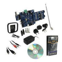
BOARD EVAL FOR SI270X-A
Manufacturer
Silicon Laboratories Inc
Datasheet
1.SI2704-A10-GM.pdf
(46 pages)
Specifications of SI270X-A-EVB
Board Type
Fully Populated
Amplifier Type
Class D
Output Type
2-Channel (Stereo) with Stereo Headphones
Max Output Power X Channels @ Load
5W x 2 @ 3 Ohm
Voltage - Supply
9V
Utilized Ic / Part
SI270X-A
Description/function
Audio Amplifiers
Output Power
5 W
Product
Audio Modules
For Use With/related Products
Si270x
Lead Free Status / RoHS Status
Lead free / RoHS Compliant
Operating Temperature
-
Lead Free Status / Rohs Status
Lead free / RoHS Compliant
Other names
336-1929


Si2704/05/06/07-A10
Figure 24. Time Domain Characteristics of the Audio Dynamic Range Controller
4.6.7. Hard Signal Limiter
The device implements a hard limiter to avoid exceeding the maximum modulation rate of the amplifier. The hard
limiter is always enabled.
4.6.8. DC Notch Filter
A dc notch filter with a 5 Hz corner frequency is implemented as the final function in the signal processing chain to
remove any dc component from the output signal. Each channel has a separate dc notch filter.
4.6.9. Tone and Alert Generation
The Si270x includes two independent tone generators with programmable frequencies and on/off times.
2
The output of both tone generators is fed to a mixer which combines the tones with the I
S inputs. The tones’
amplitudes can be adjusted by programming the mixer coefficients using the SET_AUDIO_INPUT_MIXER
command.
This feature allows customization of audible alarms and alerts. Programmable frequencies range from 100 Hz to
20 kHz in 100 Hz steps and on/off times range from 0 to 65 seconds in 1 ms steps and are set via the 2-Wire
interface using the properties TONE_ONE_FREQ, TONE_ONE_ON_TIME, TONE_ONE_OFF_TIME, and
TONE_ONE_AMPLITUDE
for
the
first
tone
and
TONE_TWO_FREQ,
TONE_TWO_ON_TIME,
TONE_TWO_OFF_TIME, and TONE_TWO_AMPLITUDE for the second tone.
4.7. Fault Detection and Response
To help protect the H-bridge driver and external loads, the output stage has fault detection circuitry that allows the
device to respond to over-current and over-temperature events.
The over-temperature circuitry monitors the temperature of the device and if the temperature exceeds 135 ºC a
thermal error is issued, and the output stage is shut down by transitioning the device to Standby Mode.
The over-current protection circuit constantly monitors the current of the output stage and triggers a fault alarm if
an over-current condition is detected from three different events: a short circuit across the speaker terminals, a
short circuit of any of the outputs to ground and a short circuit of any of the outputs to the supply voltage. In each
case, the detector issues a fault if the 2.5 A current threshold is exceeded. In response to this fault the device
power stage is shut down by transitioning the device to Standby Mode.
30
Rev. 0.6
Related parts for SI270X-A-EVB
Image
Part Number
Description
Manufacturer
Datasheet
Request
R

Part Number:
Description:
SMD/C°/SINGLE-ENDED OUTPUT SILICON OSCILLATOR
Manufacturer:
Silicon Laboratories Inc
Part Number:
Description:
Manufacturer:
Silicon Laboratories Inc
Datasheet:
Part Number:
Description:
N/A N/A/SI4010 AES KEYFOB DEMO WITH LCD RX
Manufacturer:
Silicon Laboratories Inc
Datasheet:
Part Number:
Description:
N/A N/A/SI4010 SIMPLIFIED KEY FOB DEMO WITH LED RX
Manufacturer:
Silicon Laboratories Inc
Datasheet:
Part Number:
Description:
N/A/-40 TO 85 OC/EZLINK MODULE; F930/4432 HIGH BAND (REV E/B1)
Manufacturer:
Silicon Laboratories Inc
Part Number:
Description:
EZLink Module; F930/4432 Low Band (rev e/B1)
Manufacturer:
Silicon Laboratories Inc
Part Number:
Description:
I°/4460 10 DBM RADIO TEST CARD 434 MHZ
Manufacturer:
Silicon Laboratories Inc
Part Number:
Description:
I°/4461 14 DBM RADIO TEST CARD 868 MHZ
Manufacturer:
Silicon Laboratories Inc
Part Number:
Description:
I°/4463 20 DBM RFSWITCH RADIO TEST CARD 460 MHZ
Manufacturer:
Silicon Laboratories Inc
Part Number:
Description:
I°/4463 20 DBM RADIO TEST CARD 868 MHZ
Manufacturer:
Silicon Laboratories Inc
Part Number:
Description:
I°/4463 27 DBM RADIO TEST CARD 868 MHZ
Manufacturer:
Silicon Laboratories Inc
Part Number:
Description:
I°/4463 SKYWORKS 30 DBM RADIO TEST CARD 915 MHZ
Manufacturer:
Silicon Laboratories Inc
Part Number:
Description:
N/A N/A/-40 TO 85 OC/4463 RFMD 30 DBM RADIO TEST CARD 915 MHZ
Manufacturer:
Silicon Laboratories Inc
Part Number:
Description:
I°/4463 20 DBM RADIO TEST CARD 169 MHZ
Manufacturer:
Silicon Laboratories Inc