ADNB-6031-EV Avago Technologies US Inc., ADNB-6031-EV Datasheet
ADNB-6031-EV
Specifications of ADNB-6031-EV


Related parts for ADNB-6031-EV


ADNB-6031-EV Summary of contents
Page 1
... LED-based optical navigation. Its high-performance, low power architecture is capable of sensing high- speed mouse motion while prolonging battery life, two performance areas essential in demanding cordless applications. ADNB-6031-EV and ADNB-6032-EV Low Power Laser Mouse Bundles include: Bundle Part Number Part Number ADNB-6031-EV ADNS-6030 ...
Page 2
... Overview of Laser Mouse Sensor Assembly Figure 1. 2D Assembly drawing of ADNB-6032-EV (top and cross-sectional view) 2 ...
Page 3
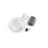
... Assembly Drawing of ADNB-6031-EV/32, PCBs and Base Plate *or ADNS-6120 for round lens Figure 2. Exploded view drawing Shown with ADNS-6130-001 Laser Mouse Lens, ADNS- 6230-001 VCSEL Assembly Clip and ADNV-6340 VCSEL. The components interlock as they are mounted onto defined features on the base plate. ...
Page 4
Figure 3. Recommended PCB mechanical cutouts and spacing Assembly Recommendation 1. Insert the sensor and all other electrical components into the application PCB (main PCB board and VCSEL PCB board). 2. Wave-solder the entire assembly in a no-wash sol- der ...
Page 5
Design considerations for improving ESD Performance For improved electrostatic discharge performance, typical creepage and clearance distance are shown in the table below. Assumption: base plate construction as per the Avago Technologies supplied IGES file and ADNS-6130- 001 trim lens (or ...
Page 6
ADNS-6030 MAX1722 MC68HC908QY4 6 MC68HC908JB12 ...
Page 7
LASER Drive Mode The laser is driven in pulsed mode during normal operation. A calibration mode is provided which drives the laser in continuous (CW) operation. Eye Safety The ADNS-6030 and the associated components in the schematic of Figure 5 ...
Page 8
Parameter Symbol Minimum Laser Output Power LOP LASER Output Power The laser beam output power as measured at the navigation surface plane is specified below. The following conditions apply: 1. The system is adjusted according to the above pro- cedure. ...
Page 9
ADNS - 6030 Laser Mouse Sensor Theory of Operation LaserStream The ADNS-6030 is based on which measures changes in position by optically acquiring sequential surface images (frames) and mathematically determining the direction and magnitude of movement. The ADNS-6030 contains an ...
Page 10
Figure 8. Package outline drawing CAUTION advised that normal static precautions be taken in handling and assembly of this component to prevent damage and/or degradation which may be induced by ESD 10 ...
Page 11
ADNS-6030 VDD AVDD Image Array GND DSP AGND Oscillator LASER Drive XY_LASER Figure 9. Block Diagram of ADNS-6030 optical module sensor Absolute Maximum Ratings Parameter Symbol Storage Temperature T S Lead Solder Temp Supply Voltage V DD ESD Input Voltage ...
Page 12
Recommended Operating Conditions Parameter Symbol Operating Temperature T A Power supply voltage V DD Power supply rise time V RT Supply noise V NA (Sinusoidal) Serial Port Clock f SCLK Frequency Distance from lens Z reference plane to surface Speed ...
Page 13
AC Electrical Specifications Electrical Characteristics over recommended operating conditions. Typical values at 25 °C, V Parameter Symbol Motion delay after reset t MOT-RST Shutdown t STDWN Wake from shutdown t WAKEUP Forced Rest enable t REST-EN Wake from Forced Rest ...
Page 14
DC Electrical Specifications Electrical Characteristics over recommended operating conditions. Typical values at 25 °C, V Parameter Symbol Minimum DC Sup- I DD_RUN ply Current I DD_REST1 in various I DD_REST2 modes I DD_REST3 Peak Supply Current Shutdown I DDSTDWN Supply ...
Page 15
Typical Performance Characteristics Typical Resolution vs. Z 1000 900 800 700 600 500 400 300 200 100 0 1.5 1.6 1.7 1.8 1.9 2.0 2.1 2.2 2.3 2.4 2.5 2.6 2.7 2.8 2.9 3.0 3.1 3.2 3.3 Distance from Lens ...
Page 16
Power management modes The ADNS-6030 has three power-saving modes. Each mode has a different motion detection period, affecting response time to mouse motion (Response Time). The sensor automatically changes to the appropriate mode, depending on the time since the last ...
Page 17
Write Operation Write operation, defined as data going from the micro- controller to the ADNS-6030, is always initiated by the micro-controller and consists of two bytes. The first byte contains the address (seven bits) and has a “1” as its ...
Page 18
Required timing between Read and Write Commands There are minimum timing requirements between read and write commands on the serial port. If the rising edge of the SCLK for the last data bit of the second write command occurs before ...
Page 19
SCLK Motion_Burst Register Address Read First Byte First Read Operation Figure 21. Motion Burst Timing State of Signal Pins After VDD is Valid Pin On Power-Up NCS Functional MISO Undefined SCLK Ignored MOSI Ignored XY_LASER Undefined MOTION Undefined LASER_NEN Undefined ...
Page 20
Registers The ADNS-6030 registers are accessible via the serial port. The registers are used to read motion data and status as well as to set the device configuration. Address Register 0x00 Product_ID 0x01 Revision_ID 0x02 Motion 0x03 Delta_X 0x04 Delta_Y ...
Page 21
Product_ID Access: Read Bit 7 6 Field PID PID 7 6 Data Type : 8-Bit unsigned integer USAGE : This register contains a unique identification assigned to the ADNS-6030. The value in this register does not change; it can be ...
Page 22
Motion Access: Read/Write Bit 7 6 Field MOT PIXRDY Data Type : Bit field. USAGE : Register 0x02 allows the user to determine if motion has occurred since the last time it was read. If the MOT bit is set, ...
Page 23
Delta_X Access: Read Bit 7 6 Field Data Type : Eight bit 2’s complement number. USAGE : X movement is counts since last report. Absolute value is determined by resolution. Reading clears the register. -128 -127 ...
Page 24
SQUAL Access: Read Bit 7 6 Field Data Type : Upper 8 bits of a 9-bit unsigned integer. USAGE : SQUAL (Surface Quality measure of the number of valid features visible by the sensor ...
Page 25
Shutter_Upper Access: Read Bit 7 6 Field Shutter_Lower Access: Read Bit 7 6 Field Data Type : Sixteen bit unsigned integer. USAGE : Units are clock cycles. Read Shutter_Upper first, then Shutter_Lower. ...
Page 26
Maximum_Pixel Access: Read Bit 7 6 Field Data Type : Eight-bit number. USAGE : Maximum Pixel value in current frame. Minimum value = 0, maximum value = 254. The maximum pixel value can vary with every ...
Page 27
Pixel_Grab Access: Read/Write Bit 7 6 Field Data Type : Eight-bit word. USAGE : For test purposes, the sensor will read out the contents of the pixel array, one pixel per frame. To start a pixel ...
Page 28
CRC0 Access: Read Bit 7 6 Field CRC0 CRC0 7 6 Data Type : Eight-bit number USAGE : Register 0x0c reports the first byte of the system self test results. Value = 05. CRC1 Access: Read Bit 7 6 Field ...
Page 29
Self_Test Access: Write Bit 7 6 Field Reserved Reserved Data Type : Bit field USAGE : Set the TESTEN bit in register 0x10 to start the system self-test. The test takes 250ms. During this time, do not write or read ...
Page 30
LASER_CTRL0 Access: Read/Write Bit 7 6 Field Range Reserved Data Type : Bit field USAGE : This register is used to control the laser drive. Bits 5 and 7 require complement values in register 0x1F. If the registers do not ...
Page 31
LSRPWR_CFG0 Access: Read and Write Bit 7 6 Field Data Type : 8 Bit unsigned USAGE : This register is used to set the laser current used together with register 0x1D, where ...
Page 32
LASER_CTRL1 Access: Read and Write Bit 7 6 Field Range_C Reserved Data Type : 8 Bit unsigned USAGE : Bits 5 and 7 of this register must be the complement of the corresponding bits in register 0x1A for the VCSEL ...
Page 33
POWER_UP_RESET Access: Write Bit 7 6 Field RST RST 7 6 Data Type : 8-bit integer USAGE : Write 0x5a to this register to reset the chip. All settings will revert to default values. Reset is required after recovering from ...
Page 34
Motion_Burst Access: Read Bit 7 6 Field Data Type : Various. USAGE : Read from this register to activate burst mode. The sensor will return the data in the Motion register, Delta_X, Delta_Y, Squal, Shutter_Upper, Shutter_Lower, ...
Page 35
ADNV-6340 Single-Mode Vertical-Cavity Surface Emitting Laser (VCSEL) Description This advanced class of VCSELs was engineered by Avago Technologies to provide a laser diode with a single longitudinal and a single transverse mode. In contrast to most oxide-based single-mode VCSELs, this ...
Page 36
For cable or wire connections (2X) Dimension in millimeters Figure 28. Suggested ADNV-6340 PCB Mounting Guide Comments: 1. Stresses greater than those listed under “Absolute Maximum Ratings” may cause permanent damage to the device. These are the ...
Page 37
Optical/Electrical Characteristics ( 5°C to 45°C): Parameter Peak Wavelength [1] Maximum Radiant Power Wavelength Temperature coefficient Wavelength Current coefficient Beam Divergence Threshold current Slope Efficiency [2] Forward Voltage Notes: 1. Maximum output power under any condition. This is ...
Page 38
Forward Current, If (mA) Figure 30. Optical Power vs. Forward Current Junction Temperature rise vs. CW current ...
Page 39
ADNS-6120 and ADNS-6130-001 Laser Mouse Lens Description The ADNS-6120 and ADNS-6130-001 laser mouse lens are designed for use with Avago Technologies’ laser mouse sensors and the illumination subsystem provided by the ADNS-6230-001 VCSEL assembly clip and the ADNV-6340 Single-Mode Vertical-Cavity ...
Page 40
Max +0.2mm protrusion is allowed at the molding gate of either 1 side of lens. Figure 34. ADNS-6130-001 laser mouse trim lens outline drawings and details 40 ...
Page 41
MOUSE SENSOR LID ADNS-6120 A OBJECT SURFACE Figure 35. Optical system assembly cross-section diagram Mechanical Assembly Requirements All specifications reference Figure 35, Optical System Assembly Diagram Parameter Symbol Distance from Object Surface to A Lens Reference Plane Distance from Mouse ...
Page 42
Lens Design Optical Performance Specifications All specifications are based on the Mechanical Assembly Requirements. Parameters Design Wavelength Lens Material* Index of Refraction *Lens material is polycarbonate. Cyanoacrylate based adhesives should not be used as they will cause lens material deformation. ...
Page 43
ADNS-6230-001 Laser Mouse VCSEL Assembly Clip Description The ADNS-6230-001 VCSEL Assembly Clip is designed to provide mechanical coupling of the ADNV-6340 VCSEL to the ADNS-6120 or ADNS-6130-001 Laser Mouse Lens. This coupling is essential to achieve the proper illumination alignment ...
Page 44
For product information and a complete list of distributors, please go to our web site: Avago, Avago Technologies, and the A logo are trademarks of Avago Technologies Limited in the United States and other countries. Data subject to change. Copyright ...