NCR169D ON Semiconductor, NCR169D Datasheet

SCRs 400V 800mA

NCR169D

Manufacturer Part Number
NCR169D
Description
SCRs 400V 800mA
Manufacturer
ON Semiconductor
Datasheet

Specifications of NCR169D

Mounting Style
Through Hole
Package / Case
TO-92-3 (TO-226)
Lead Free Status / RoHS Status
Lead free / RoHS Compliant
NCR169D
General Purpose
Sensitive Gate
Silicon Controlled Rectifier
Reverse Blocking Thyristor
applications such as relay and lamp drivers, small motor controls, gate
drivers for larger thyristors, and sensing and detection circuits.
Supplied in a cost effective plastic TO-226AA package.
Features
Maximum ratings are those values beyond which device damage can occur.
Maximum ratings applied to the device are individual stress limit values (not
normal operating conditions) and are not valid simultaneously. If these limits are
exceeded, device functional operation is not implied, damage may occur and
reliability may be affected.
1. V
MAXIMUM RATINGS
© Semiconductor Components Industries, LLC, 2005
October, 2005 − Rev. 1
Peak Repetitive Off−State Voltage (Note 1.)
On-State RMS Current
Peak Non-Repetitive Surge Current
Circuit Fusing Consideration (t = 10 ms)
Forward Peak Gate Power
Forward Average Gate Power
Forward Peak Gate Current
Reverse Peak Gate Voltage
Operating Junction Temperature Range
Storage Temperature Range
Other Logic Circuits
Sensitive Gate Allows Direct Triggering by Microcontrollers and
On−State Current Rating of 0.8 Amperes RMS at 80°C
Surge Current Capability − 10 Amperes
Immunity to dV/dt − 20 V/μsec Minimum at 110°C
Glass-Passivated Surface for Reliability and Uniformity
Device Marking: NCR169D, Date Code
Pb−Free Packages are Available
apply for zero or negative gate voltage; however, positive gate voltage shall
not be applied concurrent with negative potential on the anode. Blocking
voltages shall not be tested with a constant current source such that the
voltage ratings of the devices are exceeded.
(T
60 Hz; Gate Open)
(T
(1/2 Cycle, Sine Wave, 60 Hz,
T
(T
(T
(T
(T
@ Rate V
DRM
PNPN device designed for line-powered general purpose
J
A
A
A
A
J
C
= 25°C)
= *40 to 110°C, Sine Wave, 50 to
= 25°C, Pulse Width v 1.0
= 25°C, t = 20 ms)
= 25°C, Pulse Width v 1.0
= 80°C) 180° Conduction Angles
and V
RRM
RRM
and V
Rating
for all types can be applied on a continuous basis. Ratings
DRM
(T
J
= 25°C unless otherwise noted)
μ
μ
μ
s)
s)
s)
Symbol
I
P
V
V
T(RMS)
V
I
P
T
G(AV)
I
DRM,
TSM
RRM
GRM
GM
T
I
GM
stg
2
J
t
−40 to
−40 to
Value
0.415
0.10
400
150
110
0.8
0.1
1.0
5.0
10
1
Amps
Volts
Volts
Unit
Amp
Watt
Watt
Amp
A
°C
°C
2
s
See detailed ordering and shipping information in the package
dimensions section on page 6 of this data sheet.
1
2
3
(TO−226AA)
A
L
Y
WW = Work Week
G
(Note: Microdot may be in either location)
K
CASE 029
STYLE 10
ORDERING INFORMATION
G
0.8 AMPERES RMS
TO−92
A
A
= Assembly Location
= Wafer Lot
= Year
= Pb−Free Package
http://onsemi.com
PIN ASSIGNMENT
400 VOLTS
SCR
Publication Order Number:
Cathode
Anode
Gate
G
MARKING
DIAGRAM
ALYWWG
1 2 3
K
169D
NCR
NCR169D/D
G

Related parts for NCR169D

NCR169D Summary of contents

Page 1

... Surge Current Capability − 10 Amperes • Immunity to dV/dt − 20 V/μsec Minimum at 110°C • Glass-Passivated Surface for Reliability and Uniformity • Device Marking: NCR169D, Date Code • Pb−Free Packages are Available MAXIMUM RATINGS (T = 25°C unless otherwise noted) J Rating Peak Repetitive Off− ...

Page 2

... Critical Rate of Rise of On−State Current = μsec; diG/dt = 1.0 A/μsec, Igt = 20 mA *Indicates Pulse Test: Pulse Width ≤ 1.0 ms, Duty Cycle ≤ 1 1000 Ohms included in measurement Does not include R in measurement. GK NCR169D (T = 25°C unless otherwise noted) C Symbol I DRM T = 25° 110° ...

Page 3

... Holding Current H 100 −40 −25 − JUNCTION TEMPERATURE (°C) J Figure 1. Typical Gate Trigger Current versus Junction Temperature NCR169D on state RRM RRM Reverse Blocking Region (off state) Reverse Avalanche Region Anode − 1.0 0.9 0.8 0.7 0.6 0.5 0.4 0.3 0 110 −40 − ...

Page 4

... Figure 3. Typical Holding Current versus Junction Temperature 120 110 100 30° 60° 0.1 0.2 0 RMS ON-STATE CURRENT (AMPS) T(RMS) Figure 5. Typical RMS Current Derating NCR169D 1000 100 110 −40 −25 − Figure 4. Typical Latching Current versus 10 MAXIMUM @ 180° 90° 120° ...

Page 5

... Holddown tape not to extend beyond the edge(s) of carrier tape and there shall be no exposure of adhesive more than 1 consecutive missing component is permitted tape trailer and leader, having at least three feed holes is required before the first and after the last component. 8. Splices will not interfere with the sprocket feed holes. NCR169D H2A H2A W2 ...

Page 6

... NCR169DRLRM Flat side of TO92 and adhesive tape visible NCR169DRLRMG Flat side of TO92 and adhesive tape visible NCR169DRLRP Flat side of TO92 and adhesive tape visible NCR169DRLRPG Flat side of TO92 and adhesive tape visible †For information on tape and reel specifications, including part orientation and tape sizes, please refer to our Tape and Reel Packaging Specifications Brochure, BRD8011/D ...

Page 7

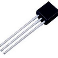
... PACKAGE DIMENSIONS SEATING K PLANE NCR169D TO−92 (TO−226AA) CASE 029−11 ISSUE AL NOTES: 1. DIMENSIONING AND TOLERANCING PER ANSI Y14.5M, 1982. 2. CONTROLLING DIMENSION: INCH. 3. CONTOUR OF PACKAGE BEYOND DIMENSION R IS UNCONTROLLED. 4. LEAD DIMENSION IS UNCONTROLLED IN P AND BEYOND DIMENSION K MINIMUM SECTION X−X STYLE 10: http://onsemi.com ...

Page 8

... USA/Canada Japan: ON Semiconductor, Japan Customer Focus Center 2−9−1 Kamimeguro, Meguro−ku, Tokyo, Japan 153−0051 Phone: 81−3−5773−3850 http://onsemi.com 8 ON Semiconductor Website: http://onsemi.com Order Literature: http://www.onsemi.com/litorder For additional information, please contact your local Sales Representative. NCR169D/D ...

Related keywords