XPSAFL5130P SQUARE D, XPSAFL5130P Datasheet - Page 115
XPSAFL5130P
Manufacturer Part Number
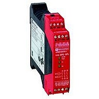
XPSAFL5130P
Description
SAFETY RELAY 300V 2.5A PREVENTA+
Manufacturer
SQUARE D
Datasheet
1.XPSMCCPC.pdf
(274 pages)
Specifications of XPSAFL5130P
Contact Current Max
30mA
Contact Voltage Dc Nom
24V
Contact Configuration
3NO
Relay Mounting
DIN Rail
External Height
66mm
External Width
114mm
External Depth
22.5mm
Rohs Compliant
Yes


10
10
1
1
2
2
3
3
4
4
5
5
6
6
7
7
8
8
9
9
Wiring diagrams
Configuration 9 (this configuration uses both functions of the controller. Only function 1 is configured).
(1) If sensors S4 and S5 are not used, terminals C4-l4 and C5-l5 must be linked.
(2) Safety outputs for tool zone.
(3) Safety outputs for rear access safety doors.
In configuration mode 9, the N.C. contacts of the relays or contactors controlled via outputs 43-44, 53-54, 63-64 cannot be monitored by the feedback loop (ESC).
ESC = External start conditions.
Configuration 9
(1) Prevention of start-up necessary: to check the sensors connected, open and reclose the guard.
Presentation:
page 2/106
Key
End of travel 1 C1-I1
End of travel 2 C2-I1
End of travel 3 C3-I1
End of travel 4 C4-I1
End of travel 5 C5-I1
Start button C6-I6
N.O. output
13-14/23-24/33-34
Signalling output Y84
N.O. output
(43-44/53-54/63-64)
Signalling output Y94
2/114
XPSMP
Guard monitoring for injection press or blowing machine
Functional diagram
+
0 V
24 V
F1
0
A2
A1
C3
C6
1
C1
C4
Power-up (Self-test accomplished)
Tool zone guard,
closed
Guard outside tool
zone, closed
S1
S4
(1)
Power-up (Self-test accomplished)
Both guards closed
Logic
channel 1
Logic
channel 2
I1
I4
Characteristics:
page 2/107
No start-up (1)
C2
(continued)
C5
S2
S5
(1)
Open
Guard for tool zone
open
S3
Safety
valve
I5
I2
Open
Function 1
Function 2
Function 1
Function 2
(F2)
(F1)
(F2)
(F1)
K11
K12
I6
I3
S6
Start
ESC
F1
t < 1,5 s
K3
K4
K2
K1
Safety automation system solutions
Preventa™ safety controllers type XPSMP
With pre-defined functions
References:
page 2/108
Both guards closed
Tool zone
K11
t < 10 s
14
13
24
23
Tool zone
K12
(2)
33
34
Dimensions:
page 2/109
Guard outside tool
zone open
43
44
t =
(3)
53
54
Both guards closed
63
64
t < 10 s
Y
+
Y74
Wiring Diagrams:
page 2/110 to 2/117
XPS MP
Y84
Y94
To PLC
Related parts for XPSAFL5130P
Image
Part Number
Description
Manufacturer
Datasheet
Request
R


Part Number:
Description:
Pushbutton, Non-Illum'd Red "STOP", Momentary, 1NO-1NC, Square 30mm, 10A, 600V
Manufacturer:
SQUARE D
Datasheet:

Part Number:
Description:
KITS,TWIDO? PROGRAMMABLE CONTROLLERS,KITS,TWIDOPACK STARTER KIT - ADVANCED LEVEL,PROGRAMMABLE CONTROLLERS,TWIDO? PROGRAMMABLE CONTROLLERS ,SQUARE D
Manufacturer:
SQUARE D

Part Number:
Description:
LAMPS,INDICATOR,STACKABLE,LAMPS, STACKABLE INDICATOR,VISUAL INDICATING SIGNALS,XVB SERIES INDICATING BANKS ,SQUARE D
Manufacturer:
SQUARE D
Part Number:
Description:
LAMPS,INDICATOR,STACKABLE,LAMPS, STACKABLE INDICATOR,VISUAL INDICATING SIGNALS,XVB SERIES INDICATING BANKS ,SQUARE D
Manufacturer:
SQUARE D
Datasheet:
Part Number:
Description:
I/O EXTENDER MODULE 4 D IN & 2 D OUTPUT
Manufacturer:
SQUARE D
Datasheet:
Part Number:
Description:
CB ACCESSORY, UNDERVOLTAGE TRIP 48V DC
Manufacturer:
SQUARE D
Datasheet: