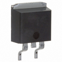
MURB820PBF Vishay, MURB820PBF Datasheet - Page 2

MURB820PBF
Manufacturer Part Number
MURB820PBF
Description
DIODE ULTRA FAST 200V 8A D2PAK
Manufacturer
Vishay
Series
FRED Pt™r
Specifications of MURB820PBF
Diode Type
Standard
Voltage - Forward (vf) (max) @ If
975mV @ 8A
Voltage - Dc Reverse (vr) (max)
200V
Current - Average Rectified (io)
8A
Current - Reverse Leakage @ Vr
5µA @ 200V
Speed
Fast Recovery =< 500ns, > 200mA (Io)
Reverse Recovery Time (trr)
35ns
Mounting Type
Surface Mount
Package / Case
D²Pak, TO-263 (2 leads + tab)
Product
Ultra Fast Recovery Rectifier
Configuration
Single
Reverse Voltage
200 V
Forward Voltage Drop
0.975 V
Recovery Time
35 ns
Forward Continuous Current
8 A
Max Surge Current
100 A
Reverse Current Ir
5 uA
Mounting Style
SMD/SMT
Maximum Operating Temperature
+ 175 C
Minimum Operating Temperature
- 65 C
Repetitive Reverse Voltage Vrrm Max
200V
Forward Current If(av)
8A
Forward Voltage Vf Max
975mV
Reverse Recovery Time Trr Max
25ns
Forward Surge Current Ifsm Max
100A
Lead Free Status / RoHS Status
Lead free / RoHS Compliant
Capacitance @ Vr, F
-
Lead Free Status / Rohs Status
Lead free / RoHS Compliant
Other names
*MURB820PBF
VS-MURB820PBF
VS-MURB820PBF
VSMURB820PBF
VSMURB820PBF
VS-MURB820PBF
VS-MURB820PBF
VSMURB820PBF
VSMURB820PBF
Available stocks
Company
Part Number
Manufacturer
Quantity
Price
Company:
Part Number:
MURB820PBF
Manufacturer:
Vishay Semiconductors
Quantity:
1 750
Document Number: 94081
MURB820PbF, MURB820-1PbF
Bulletin PD-21085 08/05
Dynamic Recovery Characteristics @ T
Thermal - Mechanical Characteristics
Electrical Characteristics @ T
t
I
Q
T
T
R
R
R
Wt
V
V
I
C
L
rr
RRM
R
J
Stg
S
thJC
thJA
thCS
BR
F
T
rr
Mounting Surface, Flat, Smooth and Greased
, V
r
Reverse Recovery Time
Peak Recovery Current
Reverse Recovery Charge
Parameters
Parameters
Breakdown Voltage,
Blocking Voltage
Forward Voltage
Reverse Leakage Current
Junction Capacitance
Series Inductance
Parameters
Max. Junction Temperature Range
Max. Storage Temperature Range
Thermal Resistance, Junction to Case
Thermal Resistance, Junction to Ambient
Thermal Resistance, Case to Heatsink
Weight
Mounting Torque
Device Marking
J
Min Typ Max Units Test Conditions
Min Typ Max Units Test Conditions
200
= 25°C (unless otherwise specified)
-
-
-
-
-
-
-
-
-
-
-
-
-
1.7
4.2
8.0
20
34
23
75
25
-
-
-
-
-
-
-
0.975
0.895
J
250
35
25
5
-
-
-
-
-
-
-
-
= 25°C (unless otherwise specified)
nC
µA
µA
nH
ns
pF
A
V
V
V
I
I
T
T
T
T
T
T
I
I
I
V
T
V
Measured lead to lead 5mm from package body
F
F
R
F
F
Min
J
J
J
J
J
J
J
- 65
- 65
R
R
6.0
5.0
= 1.0A, di
= 0.5A, I
= 100µA
= 8A
= 8A, T
= 125°C
= 125°C
= 125°C
MURB820-1
= 25°C
= 25°C
= 25°C
-
-
-
-
-
= 150°C, V
= V
= 200V
MURB820
R
Rated
J
R
0.07
= 150°C
Typ
0.5
2.0
F
= 1.0A, I
-
-
-
-
-
-
/dt = 50A/µs, V
R
= V
R
I
V
di
Rated
REC
F
Max
175
R
F
175
3.0
Case style D
Case style TO-262
= 8A
50
12
10
-
-
-
/dt = 200A/µs
.
= 160V
= 0.25A
R
= 30V
www.vishay.com
Kg-cm
°C/ W
2
Units
lbf.in
Pak
(oz)
°C
g
2


