40HFR120 Vishay, 40HFR120 Datasheet - Page 2
40HFR120
Manufacturer Part Number
40HFR120
Description
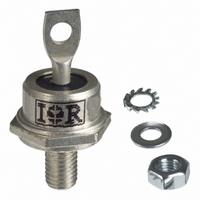
DIODE FAST REC 1200V 40A DO-5
Manufacturer
Vishay
Datasheet
1.40HF60.pdf
(7 pages)
Specifications of 40HFR120
Voltage - Forward (vf) (max) @ If
1.3V @ 125A
Voltage - Dc Reverse (vr) (max)
1200V (1.2kV)
Current - Average Rectified (io)
40A
Current - Reverse Leakage @ Vr
9mA @ 1200V
Diode Type
Standard
Speed
Standard Recovery >500ns, > 200mA (Io)
Mounting Type
Chassis, Stud Mount
Package / Case
DO-203AB, DO-5, Stud
Product
Standard Recovery Rectifier
Configuration
Single
Reverse Voltage
1200 V
Forward Voltage Drop
1.3 V at 125 A
Forward Continuous Current
40 A
Max Surge Current
595 A
Reverse Current Ir
9000 uA
Mounting Style
Stud
Maximum Operating Temperature
+ 190 C
Minimum Operating Temperature
- 65 C
Lead Free Status / RoHS Status
Lead free / RoHS Compliant
Reverse Recovery Time (trr)
-
Capacitance @ Vr, F
-
Lead Free Status / Rohs Status
Lead free / RoHS Compliant
Other names
*40HFR120
VS-40HFR120
VS-40HFR120
VS40HFR120
VS40HFR120
VS-40HFR120
VS-40HFR120
VS40HFR120
VS40HFR120


40HF(R) Series
Vishay High Power Products
Notes
(1)
(2)
www.vishay.com
2
FORWARD CONDUCTION
PARAMETER
Maximum average forward current
at case temperature
Maximum RMS forward current
Maximum peak, one-cycle forward,
non-repetitive surge current
Maximum I
Maximum I
Value of threshold voltage
(up to 1200 V)
Value of threshold voltage
(for 1400 V/1600 V)
Value of forward slope resistance
(up to 1200 V)
Value of forward slope resistance
(for 1400 V/1600 V)
Maximum forward voltage drop
THERMAL AND MECHANICAL SPECIFICATIONS
PARAMETER
Maximum junction operating and
storage temperature range
Maximum thermal resistance,
junction to case
Maximum thermal resistance,
case to heatsink
Maximum allowable mounting
torque (+ 0 %, - 10 %)
Approximate weight
Case style
Recommended for pass-through holes
Recommended for holed threaded heatsinks
2
2
t for fusing
√t for fusing
SYMBOL
SYMBOL
T
I
V
V
F(RMS)
R
I
R
J
For technical questions, contact:
I
F(AV)
V
I
FSM
F(TO)
F(TO)
, T
I
2
thJC
thCS
r
r
2
FM
√t
f
f
t
Stg
Standard Recovery Diodes,
180° conduction, half sine wave
t = 10 ms
t = 8.3 ms
t = 10 ms
t = 8.3 ms
t = 10 ms
t = 8.3 ms
t = 10 ms
t = 8.3 ms
t = 0.1 ms to 10 ms, no voltage reapplied
T
T
I
DC operation
Mounting surface, smooth, flat and greased
Not lubricated thread, tighting on nut
Lubricated thread, tighting on nut
Not lubricated thread, tighting on hexagon
Lubricated thread, tighting on hexagon
See dimensions - link at the end of datasheet
pk
J
J
= T
= T
= 125 A, T
(Stud Version), 40 A
J
J
maximum
maximum
J
No voltage
reapplied
100 % V
reapplied
No voltage
reapplied
100 % V
reapplied
= 25 °C, t
TEST CONDITIONS
TEST CONDITIONS
ind-modules@vishay.com
RRM
RRM
p
= 400 µs rectangular wave
Sinusoidal half wave,
initial T
(1)
(1)
J
(2)
= T
(2)
J
maximum
10 TO 120
10 TO 120
- 65 to 190 - 65 to 160
1.30
140
40
40HF(R)
40HF(R)
3.4 (30)
2.3 (20)
4.2 (37)
3.2 (28)
DO-203AB (DO-5)
16 000
Document Number: 93513
1600
1450
1150
1050
0.65
0.76
4.29
0.95
0.25
570
595
480
500
3.8
0.6
62
17
140/160
140/160
Revision: 25-May-09
1.50
110
40
(lbf · in)
UNITS
UNITS
N · m
A
K/W
A
mΩ
oz.
°C
°C
2
A
A
A
V
V
g
2
√s
s
Related parts for 40HFR120
Image
Part Number
Description
Manufacturer
Datasheet
Request
R

Part Number:
Description:
357-036-542-201 CARDEDGE 36POS DL .156 BLK LOPRO
Manufacturer:
Vishay
Datasheet:
Part Number:
Description:
357-036-542-201 CARDEDGE 36POS DL .156 BLK LOPRO
Manufacturer:
Vishay
Datasheet:
Part Number:
Description:
357-036-542-201 CARDEDGE 36POS DL .156 BLK LOPRO
Manufacturer:
Vishay
Datasheet:
Part Number:
Description:
357-036-542-201 CARDEDGE 36POS DL .156 BLK LOPRO
Manufacturer:
Vishay
Datasheet:
Part Number:
Description:
357-036-542-201 CARDEDGE 36POS DL .156 BLK LOPRO
Manufacturer:
Vishay
Datasheet:
Part Number:
Description:
357-036-542-201 CARDEDGE 36POS DL .156 BLK LOPRO
Manufacturer:
Vishay
Datasheet:
Part Number:
Description:
357-036-542-201 CARDEDGE 36POS DL .156 BLK LOPRO
Manufacturer:
Vishay
Datasheet:
Part Number:
Description:
357-036-542-201 CARDEDGE 36POS DL .156 BLK LOPRO
Manufacturer:
Vishay
Datasheet:
Part Number:
Description:
357-036-542-201 CARDEDGE 36POS DL .156 BLK LOPRO
Manufacturer:
Vishay
Datasheet:
Part Number:
Description:
357-036-542-201 CARDEDGE 36POS DL .156 BLK LOPRO
Manufacturer:
Vishay
Datasheet:
Part Number:
Description:
357-036-542-201 CARDEDGE 36POS DL .156 BLK LOPRO
Manufacturer:
Vishay
Datasheet:
Part Number:
Description:
357-036-542-201 CARDEDGE 36POS DL .156 BLK LOPRO
Manufacturer:
Vishay
Datasheet:
Part Number:
Description:
357-036-542-201 CARDEDGE 36POS DL .156 BLK LOPRO
Manufacturer:
Vishay
Datasheet:
Part Number:
Description:
357-036-542-201 CARDEDGE 36POS DL .156 BLK LOPRO
Manufacturer:
Vishay
Datasheet:
Part Number:
Description:
357-036-542-201 CARDEDGE 36POS DL .156 BLK LOPRO
Manufacturer:
Vishay
Datasheet: