40HFR80 Vishay, 40HFR80 Datasheet - Page 5
40HFR80
Manufacturer Part Number
40HFR80
Description
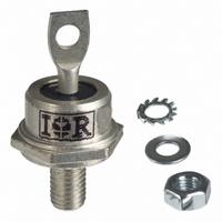
DIODE STD REC 800V 40A DO-5
Manufacturer
Vishay
Datasheet
1.40HF60.pdf
(7 pages)
Specifications of 40HFR80
Diode Type
Standard
Voltage - Forward (vf) (max) @ If
1.3V @ 125A
Voltage - Dc Reverse (vr) (max)
800V
Current - Average Rectified (io)
40A
Current - Reverse Leakage @ Vr
9mA @ 800V
Speed
Standard Recovery >500ns, > 200mA (Io)
Mounting Type
Chassis, Stud Mount
Package / Case
DO-203AB, DO-5, Stud
Product
Standard Recovery Rectifier
Configuration
Single
Reverse Voltage
800 V
Forward Voltage Drop
1.3 V at 125 A
Forward Continuous Current
40 A
Max Surge Current
595 A
Reverse Current Ir
9000 uA
Mounting Style
Stud
Maximum Operating Temperature
+ 190 C
Minimum Operating Temperature
- 65 C
Repetitive Reverse Voltage Vrrm Max
800V
Forward Current If(av)
40A
Forward Voltage Vf Max
1.3V
Forward Surge Current Ifsm Max
595A
Lead Free Status / RoHS Status
Lead free / RoHS Compliant
Reverse Recovery Time (trr)
-
Capacitance @ Vr, F
-
Lead Free Status / RoHS Status
Lead free / RoHS Compliant, Lead free / RoHS Compliant
Other names
*40HFR80
VS-40HFR80
VS-40HFR80
VS40HFR80
VS40HFR80
VS-40HFR80
VS-40HFR80
VS40HFR80
VS40HFR80


Document Number: 93513
Revision: 25-May-09
Fig. 10 - Maximum Non-Repetitive Surge Current
Fig. 9 - Maximum Non-Repetitive Surge Current
550
500
450
400
350
300
250
200
150
100
600
550
500
450
400
350
300
250
200
150
100
Number Of Equal Amplitude Half Cycle Current Pulses (N)
0.01
1
Maximum Non Repetitive Surge Current
At Any Rated Load Condition And With
40HF(R) Series
40HF(R) Series
Rated Vrrm Applied Following Surge.
Pulse Train Duration (s)
Versus Pulse Train Duration.
70
60
50
40
30
20
10
0
0
RMS Limit
Rated Vrrm Reapplied
10
No Voltage Reapplied
0.1
10
Initial Tj = Tj Max.
@ 60 Hz 0.0083 s
@ 50 Hz 0.0100 s
180°
120°
Initial Tj = Tj Max.
DC
90°
60°
30°
Average Forward Current (A)
For technical questions, contact:
20
30
Fig. 8 - Forward Power Loss Characteristics
Standard Recovery Diodes,
40HF(R) Series
(1400V, 1600V)
Tj = 160°C
100
Conduction Period
40
(Stud Version), 40 A
1
50
60
70
0
Maximum Allowable Ambient Temperature (°C)
ind-modules@vishay.com
40
80
1000
1000
Fig. 11 - Forward Voltage Drop Characteristics
Fig. 12 - Forward Voltage Drop Characteristics
100
100
10
10
Vishay High Power Products
1
1
0.5 1 1.5 2 2.5 3 3.5 4 4.5 5
0
120
Tj = Tj Max
0.5
Instantaneous Forward Voltage (V)
Instantaneous Forward Voltage (V)
(For 1400 V/1600 V)
1
(Up To 1200 V)
Tj = 25°C
160
1.5
Tj = 25°C
Tj = Tj Max.
40HF(R) Series
40HF(R) Series
up to 1200V
2
40HF (R) Series
2.5
3
3.5
www.vishay.com
4
5
Related parts for 40HFR80
Image
Part Number
Description
Manufacturer
Datasheet
Request
R

Part Number:
Description:
THYRISTOR, 235A, 600V, TO-209AB
Manufacturer:
Powerex Inc
Datasheet:

Part Number:
Description:
DIODE SCHOTTKY 10A 100V SMPC
Manufacturer:
Vishay
Datasheet:

Part Number:
Description:
357-036-542-201 CARDEDGE 36POS DL .156 BLK LOPRO
Manufacturer:
Vishay
Datasheet:
Part Number:
Description:
357-036-542-201 CARDEDGE 36POS DL .156 BLK LOPRO
Manufacturer:
Vishay
Datasheet:
Part Number:
Description:
357-036-542-201 CARDEDGE 36POS DL .156 BLK LOPRO
Manufacturer:
Vishay
Datasheet:
Part Number:
Description:
357-036-542-201 CARDEDGE 36POS DL .156 BLK LOPRO
Manufacturer:
Vishay
Datasheet:
Part Number:
Description:
357-036-542-201 CARDEDGE 36POS DL .156 BLK LOPRO
Manufacturer:
Vishay
Datasheet:
Part Number:
Description:
357-036-542-201 CARDEDGE 36POS DL .156 BLK LOPRO
Manufacturer:
Vishay
Datasheet:
Part Number:
Description:
357-036-542-201 CARDEDGE 36POS DL .156 BLK LOPRO
Manufacturer:
Vishay
Datasheet:
Part Number:
Description:
357-036-542-201 CARDEDGE 36POS DL .156 BLK LOPRO
Manufacturer:
Vishay
Datasheet:
Part Number:
Description:
357-036-542-201 CARDEDGE 36POS DL .156 BLK LOPRO
Manufacturer:
Vishay
Datasheet:
Part Number:
Description:
357-036-542-201 CARDEDGE 36POS DL .156 BLK LOPRO
Manufacturer:
Vishay
Datasheet:
Part Number:
Description:
357-036-542-201 CARDEDGE 36POS DL .156 BLK LOPRO
Manufacturer:
Vishay
Datasheet:
Part Number:
Description:
357-036-542-201 CARDEDGE 36POS DL .156 BLK LOPRO
Manufacturer:
Vishay
Datasheet:
Part Number:
Description:
357-036-542-201 CARDEDGE 36POS DL .156 BLK LOPRO
Manufacturer:
Vishay
Datasheet: