G6W-1P DC24 Omron, G6W-1P DC24 Datasheet
G6W-1P DC24
Specifications of G6W-1P DC24
G6W1PDC24
Z2049


Related parts for G6W-1P DC24


G6W-1P DC24 Summary of contents
Page 1
... PCBs. • RoHS Compliant. Ordering Information Classification SPDT Fully sealed Through-hole terminal Surface-mount terminal Note: When ordering, add the rated coil voltage to the model number. Example: G6W-1P DC12 Rated coil voltage Model Number Legend: G6W - - Relay function None: Non-latching ...
Page 2
... Single-coil Latching Relays (G6WU-1F, G6WU-1P) Rated voltage Rated current Coil resistance Must set voltage Must reset voltage Maximum voltage Power consumption Dual-coil Latching Relays (G6WK-1F, G6WK-1P) Rated voltage Rated current Coil resistance Must set voltage Must reset voltage Maximum voltage Power consumption Note: 1. The rated current and coil resistance are measured at a coil temperature of 23° ...
Page 3
... High-frequency Relay Dual-coil latching G6WK-1F, G6WK-1P Shock Malfunction Y 1,000 Energized 800 600 X Z 1,000 Not 1,000 400 energized 200 200 400 1,000 1,000 Z' X' 600 Shock direction 800 Unit: m/s Y 1,000 Z Sample: G6WK-1P 4.5 VDC Y' Number of Relays G6W 329 ...
Page 4
... Operating frequency (×10 operations) Electrical Endurance, AC Load: Contact Resistance (See notes 1 and 2) 1,000 Sample: G6WU-1P 9 VDC NO contact Number of Relays: 5 Test conditions: NC contact 500 10-mA resistive load at 30-VAC Switching frequency: 1,800 operations/h 300 100 50 Contact resistance 30 10 0.001 0.01 ...
Page 5
... N.C. 120 0 1,000 2,000 3,000 4,000 5,000 6,000 Frequency (MHz) Must Set and Must Reset Time Distribution (see note 1). 20 Sample: Must set time G6WK-1P 4.5 VDC Number of Relays: 20 Must reset time 0.5 1.0 1.5 2.0 2.5 3.0 3.5 Time (ms) Note: 1. The tests were conducted at an ambient temperature of 23° ...
Page 6
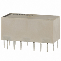
... Thirteen, 1-dia. Thirteen, 1.8-dia. 3 5.9 8.6 Through-hole 19 0.8-dia. 1.6-dia. Terminal Arrangement/ Internal Connections (Bottom View) G6W-1P Orientation mark 5.08 7.62 − G6WU-1P Orientation mark − − Terminal Arrangement/ Internal Connections (Top View) G6WK-1F Orientation mark 3 − ...
Page 7
... Relay is reset before shipping. If excessive vibration or shock is imposed, however, the Latching Relay may be set accidentally. Be sure to apply a reset signal before use. Incorrect Soldering Excessive Insufficient amount of amount of solder solder Solder Land Direction A: 4.90 N max. Direction B: 9.80 N max. Direction C: 9.80 N max. G6W High-frequency Relay 333 ...
Page 8
... High-frequency Characteristics Measurement Method and Substrate to be Measured High-frequency Characteristics for G6W are measured as shown below. G6W-1 Vector network analyzer (Manufacture: Agilent Technologies) HP8753D Through-hole substrate Substrate: t-0.8 BT resin (Dielectric constant at 2 GHz: 3.37) 1.5 0.5 0.5 Through-hole 1.8 1.5 45° ...
Page 9
... DISCONTINUED High-frequency Relay MEMO G6W ...
Page 10
... To convert millimeters into inches, multiply by 0.03937. To convert grams into ounces, multiply by 0.03527. OMRON ELECTRONIC COMPONENTS LLC 55 E. Commerce Drive, Suite B Schaumburg, IL 60173 847-882-2288 12/10 Cat. No. X302-E-1 G6W High-frequency Relay DISCONTINUED OMRON ON-LINE Global - http://www.omron.com USA - http://www.components.omron.com Specifications subject to change without notice Printed in USA ...