IXBK55N300 IXYS, IXBK55N300 Datasheet

IGBT 3000V 130A 625W TO264

IXBK55N300

Manufacturer Part Number
IXBK55N300
Description
IGBT 3000V 130A 625W TO264
Manufacturer
IXYS
Series
BIMOSFET™r
Datasheet

Specifications of IXBK55N300

Voltage - Collector Emitter Breakdown (max)
3000V
Vce(on) (max) @ Vge, Ic
3.2V @ 15V, 55A
Current - Collector (ic) (max)
130A
Power - Max
625W
Input Type
Standard
Mounting Type
Through Hole
Package / Case
TO-264
Vces, (v)
3000
Ic25, Tc=25°c, (a)
130
Ic90, Tc=90°c, (a)
55
Ic110, Tc=110°c, (a)
-
Vce(sat), Typ, Tj=25°c, (v)
3.2
Tf Typ, Tj=25°c, (ns)
268
Tfi Typ, Tj=25°c, (ns)
-
Gate Drive, (v)
-
Rthjc, Max, (k/w)
0.20
Package Style
TO-264
Lead Free Status / RoHS Status
Lead free / RoHS Compliant
Igbt Type
-
High Voltage, High Gain
BiMOSFET
Monolithic Bipolar
MOS Transistor
Symbol
V
V
V
V
I
I
I
I
SSOA
(RBSOA)
T
(SCSOA)
P
T
T
T
T
T
M
F
Weight
Symbol
(T
BV
V
I
I
V
© 2009 IXYS CORPORATION, All Rights Reserved
C25
LRMS
C110
CM
CES
GES
SC
J
JM
stg
L
SOLD
C
CES
CGR
GES
GEM
C
GE(th)
CE(sat)
d
J
CES
= 25°C, Unless Otherwise Specified)
Continuous
Transient
T
T
T
T
V
Clamped Inductive Load
V
R
T
Maximum Lead Temperature for Soldering
1.6 mm (0.062 in.) from Case for 10
Mounting Torque (TO-264 )
Mounting Force (PLUS247 )
TO-264
PLUS247
I
I
V
V
I
Test Conditions
T
T
Test Conditions
C
C
C
C
C
C
C
C
J
J
GE
GE
CE
CE
G
= 25°C to 150°C, R
= 25°C to 150°C
= 25°C ( Chip Capability )
= 25°C ( Lead RMS Limit )
= 110°C
= 25°C, 1ms
= 15V, T
= 25°C
= 10Ω, V
= 15V, T
= 1mA, V
= 4mA, V
= V
= 0V, V
= 55A, V
TM
CES
, V
VJ
GE
J
CE
GE
GE
= 125°C,
CE
= 125°C, R
GE
= ± 25V
= 1250V, Non-Repetitive
= 15V, Note 1
= 0V
= V
= 0V
GE
GE
= 1MΩ
G
= 2Ω
T
Advance Technical Information
T
J
J
= 125°C
= 125°C
IXBK55N300
IXBX55N300
20..120/4.5..27
3000
Min.
Characteristic Values
@0.8 • V
3.0
-55 ... +150
-55 ... +150
Maximum Ratings
I
CM
1.13/10
= 110
3000
3000
±25
300
±35
130
120
150
260
430
625
Typ.
CES
10
10
55
3.3
2.7
6
±200 nA
Nm/lb.in.
Max.
5.0
3.2
50 μA
3 mA
N/lb.
°C
°C
°C
°C
μs
°C
W
V
V
V
V
A
A
A
A
V
V
V
A
V
g
g
V
I
V
TO-264 (IXBK)
PLUS247
G = Gate
E = Emitter
Features
Applications
Advantages
C110
High Blocking Voltage
International Standard Packages
Low Conduction Losses
High Current Handling Capability
MOS Gate Turn-On
- Drive Simplicity
Uninterruptible Power Supplies (UPS)
Switched-Mode and Resonant-Mode
Power Supplies
Capacitor Discharge Circuits
Laser Generators
Easy to Mount
Space Savings
High Power Density
CE(sat)
CES
G
C
G
E
C
TM
E
≤ ≤ ≤ ≤ ≤ 3.2V
= 3000V
= 55A
(IXBX)
C
TAB = Collector
= Collector
DS100158(06/09)
(TAB)
(TAB)

Related parts for IXBK55N300

IXBK55N300 Summary of contents

Page 1

... CES CE CES 0V ± 25V GES 55A 15V, Note 1 CE(sat © 2009 IXYS CORPORATION, All Rights Reserved Advance Technical Information IXBK55N300 IXBX55N300 Maximum Ratings 3000 = 1MΩ 3000 GE ±25 ±35 130 120 55 430 = 2Ω 110 G CM @0.8 • V CES 10 625 -55 ... +150 150 -55 ... +150 ...

Page 2

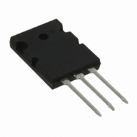
... J 585 215 260 0.15 Characteristic Values Min. Typ. 1.9 /dt = 100A/μs 54 ≤ 2%. >1200V. CE 4,931,844 5,049,961 5,237,481 6,162,665 5,017,508 5,063,307 5,381,025 6,259,123 B1 5,034,796 5,187,117 5,486,715 6,306,728 B1 IXBK55N300 IXBX55N300 TO-264 (IXBK) Outline Max 0.20 °C/W °C/W PLUS 247 (IXBX) Outline TM Max 2.5 V μs ...

Page 3

... T = 25ºC J 140 120 100 3 IXBK55N300 IXBX55N300 Fig. 2. Extended Output Characteristics @ 25º 25V GE 20V 15V 10V Volts CE Fig. 4. Dependence of V CE(sat) Junction Temperature V = 15V 110A 55A 27.5A ...

Page 4

... Fig. 8. Forward Voltage Drop of Intrinsic Diode T = 25ºC J 0.4 0.6 0.8 1.0 1.2 1.4 1.6 1.8 2 Volts F Fig. 10. Capacitance MHz Volts CE Fig. 12. Maximum Transient Thermal Impedance 0.001 0.01 0.1 Pulse Width - Seconds IXBK55N300 IXBX55N300 T = 125ºC J 2.2 2.4 2.6 2.8 3.0 C ies C oes C res ...

Page 5

... Fig. 18. Resistive Turn-off Switching Times vs. Gate Resistance d(off ) T = 125º 15V 1250V 110A Ohms G IXBK55N300 IXBX55N300 160 180 200 220 300 d(off) 280 = 15V GE 260 240 220 200 180 160 140 120 105 115 125 680 600 520 440 360 I = 220A C ...

Related keywords