IRFL9014PBF Vishay, IRFL9014PBF Datasheet

MOSFET P-CH 60V 1.8A SOT223

IRFL9014PBF

Manufacturer Part Number
IRFL9014PBF
Description
MOSFET P-CH 60V 1.8A SOT223
Manufacturer
Vishay
Type
Power MOSFETr
Datasheets

Specifications of IRFL9014PBF

Transistor Polarity
P-Channel
Fet Type
MOSFET P-Channel, Metal Oxide
Fet Feature
Standard
Rds On (max) @ Id, Vgs
500 mOhm @ 1.1A, 10V
Drain To Source Voltage (vdss)
60V
Current - Continuous Drain (id) @ 25° C
1.8A
Vgs(th) (max) @ Id
4V @ 250µA
Gate Charge (qg) @ Vgs
12nC @ 10V
Input Capacitance (ciss) @ Vds
270pF @ 25V
Power - Max
2W
Mounting Type
Surface Mount
Package / Case
SOT-223 (3 leads + Tab), SC-73, TO-261
Minimum Operating Temperature
- 55 C
Configuration
Single Dual Drain
Resistance Drain-source Rds (on)
0.5 Ohm @ 10 V
Drain-source Breakdown Voltage
60 V
Gate-source Breakdown Voltage
+/- 20 V
Continuous Drain Current
1.8 A
Power Dissipation
2000 mW
Maximum Operating Temperature
+ 150 C
Mounting Style
SMD/SMT
Continuous Drain Current Id
-1.8A
Drain Source Voltage Vds
-60V
On Resistance Rds(on)
500mohm
Rds(on) Test Voltage Vgs
-10V
Threshold Voltage Vgs Typ
-4V
Number Of Elements
1
Polarity
P
Channel Mode
Enhancement
Drain-source On-res
0.5Ohm
Drain-source On-volt
60V
Gate-source Voltage (max)
±20V
Drain Current (max)
1.8A
Output Power (max)
Not RequiredW
Frequency (max)
Not RequiredMHz
Noise Figure
Not RequireddB
Power Gain
Not RequireddB
Drain Efficiency
Not Required%
Operating Temp Range
-55C to 150C
Operating Temperature Classification
Military
Mounting
Surface Mount
Pin Count
3 +Tab
Package Type
SOT-223
Lead Free Status / RoHS Status
Lead free / RoHS Compliant
Lead Free Status / RoHS Status
Lead free / RoHS Compliant, Lead free / RoHS Compliant

Available stocks

Company
Part Number
Manufacturer
Quantity
Price
Part Number:
IRFL9014PBF
Manufacturer:
IR
Quantity:
45 200
Part Number:
IRFL9014PBF
Manufacturer:
IR
Quantity:
20 000
Description
Third Generation HEXFETs from International Rectifier
provide the designer with the best combination of fast
switching, ruggedized device design, low on-resistance
and cost-effectiveness.
The SOT-223 package is designed for surface-mount using
vapor phase, infra red, or wave soldering techniques. Its
unique package design allows for easy automatic pick-and-
place as with other SOT or SOIC packages but has the
added advantage of improved thermal performance due to
an enlarged tab for heatsinking. Power dissipation of
grreater than 1.25W is possible in a typical surface mount
application.
l Surface Mount
l Available in Tape & Reel
l Dynamic dv/dt Rating
l Repetitive Avalanche Rated
l
l Fast Switching
l Ease of Paralleling
l Lead-Free
Document Number: 91195
** When mounted on 1'' SQUARE pcb (FR-4 or G-10 Material).
Thermal Resistance
HEXFET
I
I
I
P
P
E
I
E
dv/dt
T
D
D
DM
V
AR
R
R
Absolute Maximum Ratings
J,
D
D
AS
AR
GS
θJC
θJA
For recommended footprint and soldering techniques refer to application note #AN-994.
@ Tc = 25°C
@ Tc = 100°C
@Tc = 25°C
@T
T
STG
A
= 25°C
®
Power MOSFET
Soldewring Temperature, for 10 seconds
Continuous Drain Current, V
Pulsed Drain Current 
Power Dissipation
Power Dissipation (PCB Mount)**
Linear Derating Factor
Linear Derating Factor (PCB Mount)**
Gate-to-Source Voltage
Single Pulse Avalanche Energy‚
Avalanche Current
Repetitive Avalanche Energy
Peak Diode Recovery dv/dt ƒ
Junction and Storage Temperature Range
Junction-to-PCB
Junction-to-Ambient. (PCB Mount)**
Parameter
Parameter
GS
GS
@ -10 V
@ -10 V
G
Typ.
–––
–––
300 (1.6mm from case)
D
S
-55 to + 150
SOT-223
Max.
0.025
0.017
-/+20
-4.5
-1.8
-1.1
140
-1.8
0.31
-14
2.0
3.1
R
Max.
DS(on)
V
40
60
I
DSS
D
= -1.8A
www.vishay.com
= -60V
= 0.50Ω
Units
Units
W/°C
V/ns
°C
mJ
mJ
W
V
A
1

Related parts for IRFL9014PBF

IRFL9014PBF Summary of contents

Page 1

... - - 150 300 (1.6mm from case) Typ. ––– ––– -60V DSS R = 0.50Ω DS(on -1.8A D SOT-223 Max. Units -1.8 -1.1 -14 3.1 2.0 W 0.025 0.017 W/°C -/+20 V 140 mJ -1.8 A 0.31 mJ -4.5 V/ns °C Max. Units 40 60 www.vishay.com 1 ...

Page 2

... IRFL9014PbF Electrical Characteristics @ T Parameter V Drain-to-Source Breakdown Voltage (BR)DSS ∆V Breakdown Voltage Temp. Coefficient /∆T (BR)DSS J DS(on) V Gate Threshold Voltage GS(th) g Forward Transconductance fs DSS Gate-to-Source Forward Leakage GSS Gate-to-Source Reverse Leakage Q Total Gate Charge g Q Gate-to-Source Charge gs Q Gate-to-Drain ("Miller") Charge gd t Turn-On Delay Time ...

Page 3

... Document Number: 91195 IRFL9014PbF www.vishay.com 3 ...

Page 4

... IRFL9014PbF Document Number: 91195 www.vishay.com 4 ...

Page 5

... Document Number: 91195 IRFL9014PbF www.vishay.com 5 ...

Page 6

... IRFL9014PbF Document Number: 91195 www.vishay.com 6 ...

Page 7

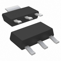
... HEXFET PRODUCT MARKING THIS IS AN IRFL014 INT ERNAT IONAL RECTIF IER LOGO Document Number: 91195 LOT CODE PART NUMBE R FL014 314P DAT E CODE EMBLY CODE (YYWW YEAR WW = WEEK SIGNATES LEAD-F REE PRODUCT (OPTIONAL) IRFL9014PbF AXXXX BOT TOM www.vishay.com 7 ...

Page 8

... IRFL9014PbF 2.05 (.080) 1.95 (.077) TR FEED DIRECTION NOTES : 1. CONTROLLING DIMENSION: MILLIMETER. 2. OUTLINE CONFORMS TO EIA-481 & EIA-541. 3. EACH O330.00 (13.00) REEL CONTAINS 2,500 DEVICES. 13.20 (.519) 12.80 (.504) 330.00 (13.000) MAX. NOTES : 1. OUTLINE COMFORMS TO EIA-418-1. 2. CONTROLLING DIMENSION: MILLIMETER.. 3. DIMENSION MEASURED @ HUB. 4. INCLUDES FLANGE DISTORTION @ OUTER EDGE. ...

Page 9

... Except as provided in Vishay's terms and conditions of sale for such products, Vishay assumes no liability whatsoever, and disclaims any express or implied warranty, relating to sale and/or use of Vishay products including liability or warranties relating to fitness for a particular purpose, merchantability, or infringement of any patent, copyright, or other intellectual property right. ...

Related keywords