IRF6709S2TRPBF International Rectifier, IRF6709S2TRPBF Datasheet
IRF6709S2TRPBF
Specifications of IRF6709S2TRPBF
Available stocks


Related parts for IRF6709S2TRPBF

IRF6709S2TRPBF Summary of contents
Page 1
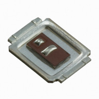
... The IRF6709S2TRPbF has low charge along with ultra low package inductance providing significant reduction in switching losses. The reduced losses make this product ideal for high efficiency DC-DC converters that power the latest generation of processors operating at higher frequencies. The IRF6709S2TRPbF has been optimized for the control FET socket of synchronous buck operating from 12 volt bus converters. ...
Page 2
Static @ T = 25°C (unless otherwise specified) J Parameter BV Drain-to-Source Breakdown Voltage DSS ∆ΒV /∆T Breakdown Voltage Temp. Coefficient DSS J R Static Drain-to-Source On-Resistance DS(on) V Gate Threshold Voltage GS(th) ∆V /∆T Gate Threshold Voltage Coefficient GS(th) ...
Page 3
Absolute Maximum Ratings 25°C Power Dissipation 70°C Power Dissipation 25°C Power Dissipation Peak Soldering Temperature P T Operating Junction and J T Storage Temperature ...
Page 4
PULSE WIDTH Tj = 25°C 0.01 0 Drain-to-Source Voltage (V) Fig 4. Typical Output Characteristics 1000 15V ≤ 60µs PULSE WIDTH 100 175°C ...
Page 5
175° 25° -40° 0.2 0.3 0.4 0.5 0.6 0.7 0.8 0.9 1.0 1.1 1 Source-to-Drain Voltage (V) Fig 10. Typical Source-Drain Diode Forward Voltage ...
Page 6
Duty Cycle = Single Pulse 10 0.01 1 0.05 0.10 0.1 Allowed avalanche Current vs avalanche pulsewidth, tav, assuming ∆ 25°C and Tstart = 150°C. 0.01 1.0E-06 1.0E-05 Fig 16. Typical Avalanche Current Vs.Pulsewidth 60 TOP Single ...
Page 7
DUT 0 1K 20K S Fig 18a. Gate Charge Test Circuit D.U 20V 0.01 Ω Fig 19a. Unclamped Inductive Test Circuit ≤ 1 ≤ 0.1 % Fig 20a. Switching Time Test ...
Page 8
D.U.T + ƒ • • - • + ‚ „ • G • • SD • Fig 19. ™ 8 Driver Gate Drive Period P.W. D.U.T. I Waveform SD Reverse Recovery Body Diode Forward Current + D.U.T. ...
Page 9
Please see AN-1035 for DirectFET assembly details and stencil and substrate design recommendations DirectFET™ Part Marking www.irf.com DIMENSIONS METRIC IMPERIAL CODE MAX MIN MIN MAX A 4.75 4.85 0.187 0.191 3.95 0.146 B 3.70 0.156 2.85 C 0.108 2.75 ...
Page 10
DirectFET™ Tape & Reel Dimension (Showing component orientation). NOTE: CONTROLLING DIMENSIONS WORLD HEADQUARTERS: 233 Kansas St., El Segundo, California 90245, USA Tel: (310) 252-7105 NOTE: Controlling dimensions in mm Std reel quantity ...