IRFI4229PBF International Rectifier, IRFI4229PBF Datasheet
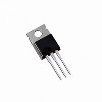
MOSFET N-CH 250V 19A TO-220FP

IRFI4229PBF

Manufacturer Part Number
IRFI4229PBF
Description
MOSFET N-CH 250V 19A TO-220FP
Manufacturer
International Rectifier
Series
HEXFET®r
Datasheet

Specifications of IRFI4229PBF

Fet Type
MOSFET N-Channel, Metal Oxide
Fet Feature
Standard
Rds On (max) @ Id, Vgs
46 mOhm @ 11A, 10V
Drain To Source Voltage (vdss)
250V
Current - Continuous Drain (id) @ 25° C
19A
Vgs(th) (max) @ Id
5V @ 250µA
Gate Charge (qg) @ Vgs
110nC @ 10V
Input Capacitance (ciss) @ Vds
4480pF @ 25V
Power - Max
46W
Mounting Type
Through Hole
Package / Case
TO-220-3 (Straight Leads)
Transistor Polarity
N-Channel
Drain-source Breakdown Voltage
250 V
Gate-source Breakdown Voltage
30 V
Continuous Drain Current
19 A
Power Dissipation
46 W
Mounting Style
Through Hole
Gate Charge Qg
73 nC
Lead Free Status / RoHS Status
Lead free / RoHS Compliant

Available stocks

Company
Part Number
Manufacturer
Quantity
Price
Part Number:
IRFI4229PBF
Manufacturer:
IR
Quantity:
12 500
Part Number:
IRFI4229PBF
Manufacturer:
IR
Quantity:
20 000
Features
l
l
l
l
l
l
l
l
Description
Notes  through … are on page 8
www.irf.com
V
I
I
I
I
P
P
T
T
R
R
Absolute Maximum Ratings
Thermal Resistance
150°C Operating Junction Temperature for
D
D
DM
RP
Energy Recovery and Pass Switch Applications
Dissipation in PDP Sustain, Energy Recovery
and Pass Switch Applications
Reliable Operation
and Reliability
Improved Ruggedness
Advanced Process Technology
Key Parameters Optimized for PDP Sustain,
Low E
Low Q
High Repetitive Peak Current Capability for
Short Fall & Rise Times for Fast Switching
Repetitive Avalanche Capability for Robustness
J
STG
GS
D
D
θJC
θJA
@ T
@ T
@T
@T
@ T
HEXFET
C
C
C
C
C
= 25°C
= 100°C
= 25°C
= 100°C
PULSE
G
= 100°C
for Fast Response
MOSFET
®
Rating to Reduce Power
Power MOSFET
Gate-to-Source Voltage
Continuous Drain Current, V
Pulsed Drain Current
Repetitive Peak Current
Power Dissipation
Power Dissipation
Linear Derating Factor
Operating Junction and
Storage Temperature Range
Soldering Temperature for 10 seconds
Mounting Torque, 6-32 or M3 Screw
Junction-to-Case
Junction-to-Ambient
f
Parameter
Parameter
f
g
MOSFET
PULSE
GS
GS
PDP SWITCH
@ 10V
@ 10V
V
V
R
I
T
RP
J
DS
DS (Avalanche)
DS(ON)
G
max
max @ T
max
Gate
G
typ. @ 10V
typ.
C
Typ.
= 100°C
–––
–––
Key Parameters
S
10lb
D
-40 to + 150
x
IRFI4229PbF
in (1.1N
Max.
0.37
300
±30
19
12
72
32
46
18
Drain
D
x
m)
MOSFET
Max.
2.73
65
TO-220AB Full-Pak
250
300
150
38
32
D
Source
S
Units
Units
W/°C
°C/W
G
°C
W
N
V
A
m
D
03/27/08
°C
V
V
A
S
1

Related parts for IRFI4229PBF

IRFI4229PBF Summary of contents

Page 1

... Notes  through … are on page 8 www.irf.com PDP SWITCH V max DS V typ. DS (Avalanche) R typ. @ 10V DS(ON) I max @ max Gate MOSFET PULSE Parameter @ 10V GS @ 10V GS g Parameter f f IRFI4229PbF Key Parameters 250 V 300 100° 150 ° TO-220AB Full-Pak D S Drain Source MOSFET Max. Units ± ...

Page 2

Electrical Characteristics @ T Parameter BV Drain-to-Source Breakdown Voltage DSS ∆ΒV /∆T Breakdown Voltage Temp. Coefficient DSS J R Static Drain-to-Source On-Resistance DS(on) V Gate Threshold Voltage GS(th) ∆V /∆T Gate Threshold Voltage Coefficient GS(th Drain-to-Source Leakage Current ...

Page 3

VGS TOP 15V 10V 8.0V 100 7.0V 6.5V 6.0V 5.5V BOTTOM 5. 0.1 5.0V ≤ 60µs PULSE WIDTH Tj = 25°C 0.01 0 Drain-to-Source Voltage (V) Fig 1. Typical Output Characteristics 100 V ...

Page 4

L = 220nH 1600 1400 C = 0.3µF 1200 1000 800 600 C = 0.1µF 400 200 100 Temperature (°C) Fig 7. Typical E vs.Temperature PULSE 7000 0V ...

Page 5

125°C 100 25° GS, Gate -to -Source Voltage (V) Fig 13. On-Resistance vs. Gate Voltage 5.0 4 ...

Page 6

D.U.T + ƒ • • - • + ‚ -  R • • • SD • Fig 18 D.U 20V V GS 0.01 Ω Fig 19a. Unclamped Inductive Test Circuit ...

Page 7

A RG DRIVER L B Ipulse RG DUT Fig 21a. t and E Test Circuit st PULSE D.U. ≤ 1 ≤ 0.1 % Fig 22a. Switching Time Test Circuit www.irf.com C VCC Fig 21b. t ...

Page 8

TO-220AB Full-Pak packages are not recommended for Surface Mount Application. Notes:  Repetitive rating; pulse width limited by max. junction temperature. ‚ Starting T = 25° 1.9mH 25Ω ƒ Pulse width ≤ 400µs; ...

Related keywords