MOD-USB-RS232 Olimex Ltd., MOD-USB-RS232 Datasheet
MOD-USB-RS232
Specifications of MOD-USB-RS232


Related parts for MOD-USB-RS232


MOD-USB-RS232 Summary of contents
Page 1
... MOD-MP3-X and MOD-MP3-X-BAT All boards produced by Olimex are ROHS compliant Copyright(c) 2011, OLIMEX Ltd, All rights reserved INTRODUCTION: development boards Users Manual Revision B, January 2011 Page 1 ...
Page 2
... The user is provided with controls on volume, sound effects, starting, stopping and sequencing of files to play. - UEXT playback mode – in this mode the board can be connected as slave device to host microcontroller which streams data to the codec via SPI. - UEXT smart control mode – in this mode the on-board microcontroller manages playback of files written to the micro SD card ...
Page 3
... The MOD-MP3-X board is shipped in protective anti-static packaging. The board must not be subject to high electrostatic potentials. General practice for working with static sensitive devices should be applied when working with this board. BOARD USE REQUIREMENTS: Cables: The cable you will need depends on the programmer/debugger you use. If you use ARM-JTAG-EW, you will need USB A-B cable, for all types programmers you will need ARM-JTAG-20to10 adapter ...
Page 4
... All mappable on 16 external interrupt vectors Atomic read/modify/write operations 4 timers 3 general purpose timers 1 advanced control timer communication interfaces interfaces (SMBus/PMBus) 3 USARTs (ISO 7816 interface, LIN, IrDA capability, modem control) 2 SPIs (18 Mbit/s) CAN interface (2.0B Active) USB 2.0 full speed interface Page and USARTs ...
Page 5
BLOCK DIAGRAM: MEMORY MAP: Page 5 ...
Page 6
AUDIO CODEC FEATURES: Page 6 ...
Page 7
Decodes Ogg Vorbis; MPEG 1 & 2 audio layer III (CBR +VBR +ABR); layers I & II optional; MPEG4 / 2 AAC-LC(+PNS), HE-AAC v2 (Level 3) (SBR + PS); WMA4.0/4.1/7/8/9 all profiles (5-384 kbps); WAV (PCM + IMA ADPCM); General ...
Page 8
AUDIO CODEC BLOCK DIAGRAM: Page 8 ...
Page 9
SCHEMATIC: 3-R 2 1-L 100nF 22 100nF DGND4 21 DGND3 20 100nF DGND2 16 DGND1 4 DGND0 C8 10uF/10V 19 IOVDD2 14 IOVDD1 6 IOVDD0 31 CVDD3 24 CVDD2 7 CVDD1 5 CVDD0 100nF 100nF 100nF 2 100nF 1 C3 ...
Page 10
BOARD LAYOUT: Page 10 ...
Page 11
... The programmed board power consumption is about 70 mA with all peripherals enabled. RESET CIRCUIT: MOD-MP3-X reset circuit for VS1053 includes RC group - R7 (100kΩ) pull- up and C12 (100nF), jumper MP3_RST, jumper VLS_RST, STM32F103RBT6 pin 43 (PA10/USART1_RX/TIM1_CH3) and VS1053 pin 3 (XRESET). Note, that if VLS_RST jumper is closed, STM32F103RBT6 must not control the VS1053 RESET, because VLS_RST is connected to ground. MOD-MP3-X reset circuit for STM32F103RBT6 includes R36 (10kΩ ...
Page 12
... UEXT. When this jumper is shorted in position BAT – the board is power supplied via BATTERY, USB or external power supply. Default state is shorted in position BAT. BOOT_E When this jumper is closed, codec is able to boot firmware from EEPROM. This is for standalone mode. Default state is closed. SA_E This jumper connects SPI2_MOSI signal with SPI1_SCK signal. Default state is closed. ...
Page 13
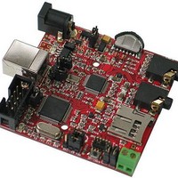
... In this mode you can use RXD and TXD signals of UEXT connector to communicate between MOD-MP3-X and your computer. For this purpose, for example, you can use our module MOD-USB-RS232, which creates a virtual COM Port. The COM Port setting are 9600bps 8N1. You can also use other our boards with UEXT to connect with MOD-MP3-X. ...
Page 14
... When in mass storage mode the LED indicates SD card read/write activity. - When playing a file in MP3 player mode LED is constantly ON. - When playback is paused in MP3 player mode LED is blinking with 0.5Hz period. Battery level status Led (yellow) with name STAT2, connected to STM32F103RBT6 pin 3 (PC14/OSC32_IN). ...
Page 15
Position SW1 (to power jack) SW2 (to headphones) SW3 (pressed) EXTERNAL CONNECTORS DESCRIPTION: PWR_JACK: Pin # Signal Name 1 Power Input 2 UEXT: Pin # Signal Name 1 +3.3V_UEXT 2 GND 3 DREQ/RXD 4 MP3_RST/TXD 5 XCS 6 SW-CS1 7 ...
Page 16
SWD: Pin # Signal Name 1 VCC (3.3V) 2 TMS/SWD 3 GND 4 TCK/SWCLK 5 GND 6 TDO 7 CUT (NC) 8 TDI 9 GND 10 RST USB: Pin # Signal Name 1 USB_DETECT 2 USBDM 3 USBDP 4 GND ...
Page 17
MIC: Pin # Signal Name 1 MICN 2 MICP/LINE1 3 MICP/LINE1 HEADPHONE: Pin # Signal Name 1 GBUF 2 RIGHT 3 LEFT SD/MMC: Pin # Signal Name 1 MCIDAT2 2 SPI2_NSS 3 SPI2_MOSI 4 VCC 5 SPI2_SCK 6 GND 7 ...
Page 18
EEPGM: Pin # Signal Name 1 VCC 2 GND 3 SPI2_MISO 4 SPI2_MOSI 5 SPI2_NSS 6 Via BOOT_E to SW-CS1 Page 18 ...
Page 19
MECHANICAL DIMENSIONS: Page 19 ...
Page 20
... AVAILABLE DEMO SOFTWARE: MOD-MP3-X-Demo Page 20 ...
Page 21
... ORDER CODE: MOD-MP3-X - How to order? You can order to us directly or by any of our distributors. Check our web Revision history: Revision B, January 2011 assembled and tested board www.olimex.com/dev for more info. Page 21 ...
Page 22
... However all warranties implied or expressed including but not limited to implied warranties of merchantability or fitness for purpose are excluded. This document is intended only to assist the reader in the use of the product. OLIMEX Ltd. shall not be liable for any loss or damage arising from the use of any information in this document or any error or omission in such information or any incorrect use of the product ...