213300-1 TE Connectivity, 213300-1 Datasheet - Page 5
213300-1
Manufacturer Part Number
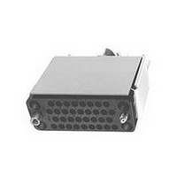
213300-1
Description
Connector Accessories Cable Connector Kit 34 POS Phenolic Black Loose Piece
Manufacturer
TE Connectivity
Type
Kitr
Series
M Seriesr
Datasheet
1.1-200867-1.pdf
(100 pages)
Specifications of 213300-1
Gender
Plug
No. Of Contacts
34
No. Of Rows
4
Contact Gender
Pin
Connector Mounting
Cable
Contact Termination
Screw
Body Material
Phenolic
Rohs Compliant
Yes
Product Type
Housing Kit
Type Of Connector
V.35
Mount
Panel
Jackscrew Type
Turnable
Mount Angle
Vertical
Jackscrew Material
Stainless Steel
Shield Material
Anodized Aluminum
Hardware Type
Jackscrew
Mounting Hardware
None
Shield Style
One-piece
Mounting Screw Material
Steel
Mounting Screw Plating
Zinc
High Voltage
No
Number Of Positions
34
Pin Hood
Without
Jackscrew Style
One-Piece
Preloaded Contacts
No
Mounting Bracket(s)
Without
Shield Size
Short
Cable Diameter Range (mm [in])
11.05 – 13.83 [0.435 – 0.545]
Cable Clamp Material
Steel
Cable Clamp Plating
Nickel
Housing Material
Phenolic - GF
Connector Style
Plug
Housing Color
Black
Rohs/elv Compliance
RoHS compliant, ELV compliant
Lead Free Solder Processes
Not relevant for lead free process
Rohs/elv Compliance History
Always was RoHS compliant
Packaging Method
Loose Piece


Catalog 82003
Revised 06-08
www.tycoelectronics.com
Dimensions are in millimeters
and inches unless otherwise
specified. Values in brackets are
equivalent U.S. Customary Units.
AMP M Series
Pin and Socket Connectors
Introduction
What makes the M Series
connector line so versatile
and special for a wide variety
of applications?
•
•
•
•
•
How to choose the appropri-
ate connector/contact/
hardware combination
Choosing the appropriate con-
nector/contact/hardware
combination is essential to the
proper function of any
AMP M Series connector. First,
a customer must evaluate
each individual application
with regards to: wire size(s);
number of circuits; available
space; fastening methods; and
needs for protection, shielding,
guiding, strain relief and key-
ing. Then, the customer must
consider the following factors
to make the appropriate selec-
tion of M Series connectors
and related components.
Compatibility
connectors intermateable
with connectors made to
MIL-C-28748 requirements.
Wide range
nector styles and sizes:
standard connectors
(unloaded), posted connec-
tors (preloaded) and special
application connectors.
Complete line
accessory hardware for fas-
tening, protecting, guiding,
strain relief and keying.
Variety of contacts
power, coaxial, and posted
versions—many are inter-
changeable and can be
intermixed in the same con-
nector housing.
Full complement of applica-
tion tooling–For wire crimp
and posted terminationshand
tools, semiautomatic tooling
and fully automatic machines
provide highly reliable, low
cost terminations to meet
production requirements.
–Choice of con-
–Most
–Full line of
(Continued)
Dimensions are shown for
reference purposes only.
Specifications subject
to change.
–Signal,
A - Determine Connector Type–
This decision is based on the
selected contact types, circuit
density requirements and, if
posted connectors are desired,
in-plant production capabilities
for wiring connectors using
hand tools or semiautomatic
tooling. Detailed specifications
of the various M Series connec-
tors are presented on the
following pages: Standard con-
nectors (pages 44 through 51),
Posted connectors (pages 52
through 60), Special
Application connectors (pages
61 through 77).
B - Determine Hardware–
This decision is based on the
selected connector types, and
the individual application
requirements for fastening, pro-
tection, shielding, guiding, strain
relief and keying. To assist cus-
tomers in determining the
proper hardware to use, hard-
ware selection information has
been formulated for each con-
nector type. This information is
located on pages 10 through 25.
Complete specifications of each
hardware component are pre-
sented in the Hard-ware section
of the catalog (pages 78
through 89).
C - Determine Contact Type –
This decision is based on wire
size(s) and reliability and cost
requirements of an application,
as well as the customer’s in-
plant production capabilities.
Complete specifications, includ-
ing accepted wire sizes and
available platings of all pin and
socket contacts, are presented
in the Contacts section of the
catalog (pages 30 through 43).
Application tooling for crimp-
and post-type contacts is
presented on pages 90 and 91).
USA: 1-800-522-6752
Canada: 1-905-470-4425
Mexico: 01-800-733-8926
C. America: 52-55-5-729-0425
NOTE: All part numbers
are RoHS Compliant
South America: 55-11-3611-1514
Hong Kong: 852-2735-1628
Japan: 81-44-844-8013
UK: 44-141-810-8967
5
Related parts for 213300-1
Image
Part Number
Description
Manufacturer
Datasheet
Request
R

Part Number:
Description:
34 PASSM KIT,M SER (CC,JS)
Manufacturer:
TE Connectivity
Datasheet:

Part Number:
Description:
Printers THERMAL PRINTER HS-SLEEVE MARKER
Manufacturer:
TE Connectivity


Part Number:
Description:
High Speed / Modular Connectors 30P HEADER ASSY
Manufacturer:
TE Connectivity
Datasheet:

Part Number:
Description:
High Speed / Modular Connectors REC 6X005P R/A LT B-PLANE HS3
Manufacturer:
TE Connectivity
Datasheet:

Part Number:
Description:
High Speed / Modular Connectors 2MM HM RCPT 50P R/A AU
Manufacturer:
TE Connectivity
Datasheet:

Part Number:
Description:
High Speed / Modular Connectors 2MM HM RCPT 50P R/A AU
Manufacturer:
TE Connectivity
Datasheet:


Part Number:
Description:
Manufacturer:
TE Connectivity
Datasheet:


Part Number:
Description:
Manufacturer:
TE Connectivity
Datasheet:

Part Number:
Description:
Manufacturer:
TE Connectivity
Datasheet:

Part Number:
Description:
Manufacturer:
TE Connectivity
Datasheet: