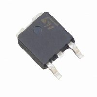
ACS120-7SB STMicroelectronics, ACS120-7SB Datasheet

ACS120-7SB
Specifications of ACS120-7SB
Available stocks
Related parts for ACS120-7SB
ACS120-7SB Summary of contents
Page 1
... It is triggered with a negative gate current flowing out of the gate pin. April 2003 - Ed +/-700V RRM = 2A T(RMS) < back on the FUNCTIONAL DIAGRAM ACS120-7SB/SFP/ST AC LINE SWITCH COM G OUT DPAK ACS120-7SB TO-220FPAB ACS120-7SFP G COM OUT TO-220AB ACS120-7ST OUT COM G COM OUT G 1/11 ...
Page 2
... ACS120-7SB/SFP/ST ABSOLUTE RATINGS (limiting values) For either positive or negative polarity of pin OUT voltage in respect to pin COM voltage Symbol Repetitive peak off-state voltage DRM RRM I RMS on-state current full cycle sine T(RMS) wave Non repetitive surge peak on-state current TSM Tj initial = 25°C, full cycle sine wave ...
Page 3
... L R =140 QII - QIII Tj=25°C L Tj=125°C Tj=25°C Tj=25°C Tj=25°C Tj=125°C Tj=125°C Tj=25°C Tj=125°C Tj=110°C Tj=125°C Tj=25°C ACS120-7SB/SFP/ST Values Unit MAX 10 mA MAX 1 V MIN 0.15 V MAX 45 mA MAX 65 mA MAX 1 ...
Page 4
... ACS120-7SB/SFP/ST AC LINE SWITCH BASIC APPLICATION The ACS120 device is well adapted to Washing machine, dishwasher, tumble drier, refrigerator, air-conditioning systems, and cookware. It has been designed especially to switch on & off low power loads such as solenoid, valve, relay, dispenser, micro-motor, pump, fan and defrost heaters. ...
Page 5
... IEC61000-4-5 standards 150 , L = 10µ 2kV SURGE VOLTAGE LINE & GENERATOR Fig. B: ACS120 switch static characteristic. . Fig. D: Current and Voltage of the ACS120 dur- ing IEC61000-4-5 standard test with R, L & OUT ACSxx COM RG = 220 ACS120-7SB/SFP/ST I OUT OUT 5/11 . ...
Page 6
... ACS120-7SB/SFP/ST OTHER FIGURES Maximum power dissipation vs RMS on state current. RMS on-state current vs ambient temperature, case temperature Relative variation of thermal impedance junction to ambient vs pulse duration and package Relative variation of gate trigger current vs junction temperature Relative variation of holding, latching and gate current vs junction ...
Page 7
... Fig. 9: Non repetitive surge peak on-state current for a sinusoidal pulse with width tp < 10ms, and corresponding value of I²t. I TSM 1000 t=20ms 100 10 1 100 1000 0.01 ACS120-7SB/SFP/ (° 100 (° 100 (A), I²t (A²s) dI/dt limitation: 50A/µS t (ms) p 0.10 1 ...
Page 8
... ACS120-7SB/SFP/ST Fig. 10: On-state characteristics (maximum values). I (A) TM 10.00 T max =0.85V to R =200m d 1.00 T =125° =25°C j 0.10 V (V) TM 0.01 0.0 0.5 1.0 1.5 2.0 ORDERING INFORMATION ACS AC Switch Number of switches 8/11 Fig. 11: Thermal resistance junction to ambient versus copper surface under tab (printed circuit board FR4, copper thickness: 35µ ...
Page 9
... PACKAGE OUTLINE MECHANICAL DATA DPAK FOOT PRINT DPAK 6.7 1.6 2.3 2.3 REF 6 1.6 ACS120-7SB/SFP/ST DIMENSIONS Millimeters Inches Min. Max Min. Max. 2.20 2.40 0.086 0.094 0.90 1.10 0.035 0.043 0.03 0.23 0.001 0.009 0.64 0.90 0.025 0.035 5.20 5.40 0.204 ...
Page 10
... ACS120-7SB/SFP/ST PACKAGE OUTLINE MECHANICAL DATA TO-220FPAB 10/11 REF Dia DIMENSIONS Millimeters Inches Min. Max. Min. Max. 4.4 4.6 0.173 0.181 2.5 2.7 0.098 0.106 2.5 2.75 0.098 0.108 0.45 0.70 0.018 0.027 0.75 1 0.030 0.039 1.15 1.70 0.045 0.067 1.15 1.70 ...
Page 11
... Diam. Package Weight DPAK 0.3 g DPAK 0.3 g TO-220FPAB 2.4 g TO-220AB 2.3 g STMicroelectronics GROUP OF COMPANIES http://www.st.com ACS120-7SB/SFP/ST DIMENSIONS Millimeters Inches Min. Max. Min. Max. 4.40 4.60 0.173 0.181 1.23 1.32 0.048 0.051 2.40 2.72 0.094 0.107 0.49 0.70 0.019 0.027 0.61 ...


