5-102618-5 TE Connectivity, 5-102618-5 Datasheet - Page 21
5-102618-5
Manufacturer Part Number
5-102618-5
Description
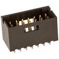
Conn Shrouded Header HDR 14 POS 2.54mm Solder ST Thru-Hole
Manufacturer
TE Connectivity
Type
Shrouded Headerr
Series
AMPMODU Mod IIr
Datasheet
1.5-87589-1.pdf
(96 pages)
Specifications of 5-102618-5
Pitch
2.54 mm
Number Of Rows
2
Number Of Contacts
14
Gender
HDR
Contact Plating
Gold Over Nickel
Termination Method
Solder
Connector Type
Wire To Board
Contact Termination
Through Hole
No. Of Contacts
14
No. Of Rows
2
Pitch Spacing
2.54mm
Rohs Compliant
Yes
Pitch (mm)
2.54mm
Number Of Contact Rows
2
Mounting Style
Through Hole
Body Orientation
Straight
Operating Temp Range
-55C to 105C
Current Rating (max)
3/ContactA
Contact Material
Phosphor Bronze
Housing Material
Thermoplastic
Housing Color
Black
Product Height (mm)
11.18mm
Product Length (mm)
20.62mm
Product Depth (mm)
10.16mm
Product Type
Connector
[shrouded] End Dimension (mm [in])
1.68 [0.066]
Mount Angle
Vertical
Pcb Mount Retention
Without
Surface Mount Compatible
No
Board Standoff
Without
Mounting Ears
Without
Mating Connector Lock
With
Mating Connector Lock Type
Detent Windows
Housing Style
4-Sided
Post Size (mm [in])
0.64 [.025]
Profile
Standard
Mating Post Length (mm [in])
8.08 [0.318]
Panel Mount Retention
Without
Termination Post Length (mm [in])
3.18 [0.125]
Solder Tail Contact Plating
Tin over Nickel
Header Type
Shrouded
Number Of Positions
14
Centerline (mm [in])
2.54 [0.100]
Row-to-row Spacing (mm [in])
2.54 [0.100]
Selectively Loaded
No
Mount Type
Printed Circuit Board
Contact Plating, Mating Area, Material
Gold (15)
Contact Shape
Square
Contact Base Material
Phosphor Bronze
Ul Flammability Rating
UL 94V-0
Rohs/elv Compliance
RoHS compliant, ELV compliant
Lead Free Solder Processes
Wave solder capable to 240°C
Rohs/elv Compliance History
Always was RoHS compliant
Operating Temperature (°c)
-55 – +105
High Temperature Housing
No
High Speed Serial Data Connector
No
Lead Free Status / Rohs Status
Compliant


.025 [0.64] Square
Right-Angle Posts
Material and Finish
Housing — Black thermoplastic, 94V-0
rated, high temperature compatible
Posts — Phosphor bronze, duplex
plated .000030 [0.00076] gold on
contact area, .000100-.000200
[0.00254-0.00508] tin on solder tail,
with entire post underplated .000050
[0.00127] nickel
Performance Characteristics
(Board Retention Tails)
Insertion Force — 12 lb [53.4N] max.
Retention Force — .25 lb [1.11N] min.
Related Product Data
Mateable Connectors —
Refer to the Mating Post Selection
Guide — page 90
Technical Documents
See mating connector for applicable
product and application specifications.
Notes: 1. Headers without retention tails may be broken to the desired number of positions using Tool Kit No. 314818-1 (not shown).
Notes:
Catalog 1307819
Revised 8-08
www.tycoelectronics.com
Retention Tails
(See Note 2.)
Solder Tails
(See Notes
With Board
1 and 2.)
Header
Style
With
2. Headers are also available in sizes 4 thru 78 positions. When ordering, add the prefix and/or suffix (dash) numbers plus 5- -0 to
the base part number that corresponds with the number of positions per row. For example, the complete part number for a 16-
position header with solder tails (C dimension .120 [3.05)] would be 5-146308-8. The complete part number for a 40-position header
with board retention tails (C dimension .120 [3.05]) would be 7-146310-0. This part numbering system applies only to this page.
No. of
— page 276
Pos.
80
80
2
2
are metric equivalents.
Dimensions are in inches and
millimeters unless otherwise
specified. Values in brackets
3.984 [101.19]
3.984 [101.19]
.084 [2.13]
.084 [2.13]
*±.003 [±0.08] tolerances not to accumulate within one connector pattern.
AMPMODU Interconnection System
Breakaway Headers—Unshrouded, Double-Row,
.100 x .100 [2.54 x 2.54] Centerline
Headers with Board Retention Tails
Note: All part numbers are RoHS compliant.
Headers with Solder Tails
A
Pattern)
(
[2.54]
Hole
.100
C L
Dimensions
(2 Plc.)
(for .062 [1.57] thick PC board; .008 [.203] thick stencil)
[1.07]
.042
(2 Plc.)
[6.05]
[1.07]
of
.042
.238
[6.05]
.238
(
*±.003 [±0.08] tolerances not to accumulate within one connector pattern.
C L
Recommended PC Board Mounting Pattern
3.900 [99.06]
3.900 [99.06]
of Hole Pattern)
[2.54]
.100
—
—
B
(for .062 [1.57] thick PC board; .008 [.203] thick stencil)
[3.81±0.05]
.150±.002
Dimensions are shown for
reference purposes only.
Specifications subject
to change.
Recommended PC Board Mounting Pattern
.100
[2.54]
[2.54]
.100*
[0.76±0.05]
.030±.002
Typ.
C = .120 [3.05]
D = .230 [5.84]
E = .185 [4.70]
[2.29±0.05] .030±.002
5-146308-1
9-146308-0
5-146310-1
9-146310-0
.090±.002
Part Nos.
.100*
[2.54]
A
B
A
B
[0.76±0.05]
[1.91]
.075
Typ.
USA: 1-800-522-6752
Canada: 1-905-470-4425
Mexico: 01-800-733-8926
C. America: 52-55-1106-0803
(Continued)
(
C = .110 [2.79]
D = .318 [8.08]
E = .200 [5.08]
C L
5-146309-1
9-146309-0
5-146311-1
9-146311-0
Part Nos.
of Stencil Pattern)
[1.14]
.045
Ref.
[4.32]
.170
Recommended Hole Size
[1.02±0.08]
[1.14±0.02]
.040±.003
.045±.001
[2.54]
[2.54]
.100
.100
(
Before Plating
C L
(Contact
E Ref.
Area)
(Plated)
(Contact
of Stencil Pattern)
Recommended Hole Size
E Ref.
Area)
[0.89±0.08]
[1.14±0.02]
.035±.003
.045±.001
[2.79]
.110
Dia. Typ.
Dia. Typ.
Before Plating
South America: 55-11-2103-6000
Hong Kong: 852-2735-1628
Japan: 81-44-844-8013
UK: 44-8706-080-208
[3.56]
.140
(Plated)
[3.56]
.140
D
D
Dia. Typ.
Dia. Typ.
using Swaged Tails
(All Header Sizes)
Board Retention
[2.54]
.100
[2.29]
.090
[2.29]
.090
[2.54]
.100
C
C
105
5
Related parts for 5-102618-5
Image
Part Number
Description
Manufacturer
Datasheet
Request
R

Part Number:
Description:
Conn Unshrouded Header HDR 10 POS 2.54mm Solder ST SMD
Manufacturer:
TE Connectivity
Datasheet:

Part Number:
Description:
Conn Shrouded Header HDR 10 POS 2.54mm Solder ST Thru-Hole
Manufacturer:
TE Connectivity
Datasheet:

Part Number:
Description:
Conn Shrouded Header HDR 10 POS 2.54mm Solder ST Thru-Hole
Manufacturer:
TE Connectivity
Datasheet:

Part Number:
Description:
Conn Unshrouded Header HDR 10 POS 2.54mm Solder ST SMD
Manufacturer:
TE Connectivity
Datasheet:

Part Number:
Description:
STACKING CONN, HEADER, 10POS, 1.27MM
Manufacturer:
TE Connectivity
Datasheet:

Part Number:
Description:
Manufacturer:
TE Connectivity
Datasheet:

Part Number:
Description:
Manufacturer:
TE Connectivity
Datasheet:

Part Number:
Description:
Conn Shrouded Header HDR 4 POS 2.54mm Solder ST Thru-Hole
Manufacturer:
TE Connectivity
Datasheet:

Part Number:
Description:
Conn Shrouded Header HDR 3 POS 2.54mm Solder RA Thru-Hole
Manufacturer:
TE Connectivity
Datasheet:

Part Number:
Description:
Conn Shrouded Header HDR 3 POS 2.54mm Solder ST Thru-Hole
Manufacturer:
TE Connectivity
Datasheet:

Part Number:
Description:
Conn Shrouded Header HDR 2 POS 2.54mm Solder ST Thru-Hole Tube
Manufacturer:
TE Connectivity
Datasheet:

Part Number:
Description:
Conn IDC Connector PIN 2 POS 2.54mm IDT ST Cable Mount Strip
Manufacturer:
TE Connectivity
Datasheet:

Part Number:
Description:
Conn IDC Connector RCP 2 POS 2.54mm IDT ST Cable Mount Strip
Manufacturer:
TE Connectivity
Datasheet:

Part Number:
Description:
Conn Shrouded Header HDR 2 POS 2.54mm Solder ST Thru-Hole Tube
Manufacturer:
TE Connectivity
Datasheet:

Part Number:
Description:
Conn Shrouded Header HDR 2 POS 2.54mm Solder ST Thru-Hole Tube
Manufacturer:
TE Connectivity
Datasheet: