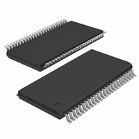
ICS9DB108BGLFT IDT, Integrated Device Technology Inc, ICS9DB108BGLFT Datasheet

ICS9DB108BGLFT
Specifications of ICS9DB108BGLFT
Available stocks
Related parts for ICS9DB108BGLFT
ICS9DB108BGLFT Summary of contents
Page 1
Integrated Circuit Systems, Inc. Eight Output Differential Buffer for PCI-Express Recommended Application: DB800 Intel Yellow Cover part with PCI-Express support. Output Features: • 0.7V current-mode differential output pairs • Supports zero delay buffer mode and fanout mode • ...
Page 2
Integrated Circuit Systems, Inc. Pin Description PIN # PIN NAME PIN TYPE 1 SRC_DIV VDD PWR 3 GND PWR 4 SRC_IN IN 5 SRC_IN OE_0 IN 7 OE_3 IN 8 DIF_0 OUT 9 DIF_0# OUT 10 ...
Page 3
Integrated Circuit Systems, Inc. Pin Description (Continued) PIN # PIN NAME PIN TYPE 25 GND PWR 26 PD SRC_STOP HIGH_BW# PWR 29 DIF_4# OUT 30 DIF_4 OUT 31 VDD PWR 32 GND PWR 33 DIF_5# OUT ...
Page 4
Integrated Circuit Systems, Inc. General Description ICS9DB108 follows the Intel DB400 Differential Buffer Specification. This buffer provides four SRC clocks for PCI-Express, next generation I/O devices. ICS9DB108 is driven by a differential input pair from a CK409/CK410 main clock generator, ...
Page 5
Integrated Circuit Systems, Inc. Absolute Max Symbol Parameter VDD_A 3.3V Core Supply Voltage VDD_In 3.3V Logic Supply Voltage V Input Low Voltage IL V Input High Voltage IH Ts Storage Temperature Tambient Ambient Operating Temp Tcase Case Temperature Input ESD ...
Page 6
Integrated Circuit Systems, Inc. Electrical Characteristics - DIF 0.7V Current Mode Differential Pair 70° 3.3 V +/-5%; C =2pF PARAMETER SYMBOL Current Source Output Zo Impedance Voltage High VHigh Voltage ...
Page 7
Integrated Circuit Systems, Inc. General SMBus serial interface information for the ICS9DB108 How to Write: • Controller (host) sends a start bit. • Controller (host) sends the write address DC • ICS clock will acknowledge • Controller (host) sends the ...
Page 8
Integrated Circuit Systems, Inc. SMBus Table: Frequency Select Register, READ/WRITE ADDRESS (DC/DD) Byte 0 Pin # Name Bit 7 - PD# drive mode - SRC_Stop# drive mode Bit 6 - Bit 5 - Bit 4 - Bit 3 - PLL_BW# ...
Page 9
Integrated Circuit Systems, Inc. SMBus Table: Output Control Register Byte 2 Pin # Name Bit 7 42,41 DIF_7 38,37 Bit 6 DIF_6 34,33 Bit 5 DIF_5 Bit 4 30,29 DIF_4 20,21 Bit 3 DIF_3 Bit 2 16,17 DIF_2 12,13 Bit ...
Page 10
Integrated Circuit Systems, Inc. SMBus Table: DEVICE ID Byte 5 Pin # Name Bit 7 - Device ID 7 (MSB) - Bit 6 - Bit 5 - Bit 4 - Bit 3 Bit Bit 1 - Bit ...
Page 11
Integrated Circuit Systems, Inc. PD#, Power Down The PD# pin cleanly shuts off all clocks and places the device into a power saving mode. PD# must be asserted before shutting off the input clock or power to insure an orderly ...
Page 12
Integrated Circuit Systems, Inc. SRC_STOP# The SRC_STOP# signal is an active-low asynchronous input that cleanly stops and starts the DIF outputs. A valid clock must be present on SRC_IN for this input to work properly. The SRC_STOP# signal is de-bounced ...
Page 13
Integrated Circuit Systems, Inc. SRC_STOP_3 (SRC_Stop = Driven Tristate) SRC_Stop# PWRDWN# DIF (Free Running) DIF# (Free Running) DIF (Stoppable) DIF# (Stoppable) SRC_STOP_4 (SRC_Stop = Tristate Tristate) SRC_Stop# PWRDWN# DIF (Free Running) DIF# (Free Running) DIF (Stoppable) ...
Page 14
Integrated Circuit Systems, Inc INDEX INDEX AREA AREA 45° SEATING SEATING b PLANE PLANE .10 (.004) C .10 (.004) C Ordering Information 9DB108yFLxT Example: XXXX ...
Page 15
Integrated Circuit Systems, Inc INDEX INDEX AREA AREA aaa Ordering Information 9DB108yGLxT Example: XXXX Designation for tape and reel packaging ...
Page 16
Integrated Circuit Systems, Inc. Revision History Rev. Issue Date Description E 10/26/2005 Updated LF Ordering Information LN. F 12/17/2000 Updated SMBus Serial Interface Information. G 12/2/2008 removed Ics prefix from ordering information 0723G—12/02/08 (Not recommended for new ...


