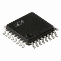
PCK942PBD,157 NXP Semiconductors, PCK942PBD,157 Datasheet - Page 9

PCK942PBD,157
Manufacturer Part Number
PCK942PBD,157
Description
IC CLCK DISTRIBUTION 1:18 32LQFP
Manufacturer
NXP Semiconductors
Type
Fanout Buffer (Distribution)r
Datasheet
1.PCK942PBD157.pdf
(11 pages)
Specifications of PCK942PBD,157
Number Of Circuits
1
Ratio - Input:output
1:18
Differential - Input:output
Yes/No
Input
LVPECL
Output
LVCMOS
Frequency - Max
250MHz
Voltage - Supply
2.375 V ~ 3.465 V
Operating Temperature
0°C ~ 70°C
Mounting Type
Surface Mount
Package / Case
32-LQFP
Frequency-max
250MHz
Number Of Outputs
18
Operating Supply Voltage (max)
3.465V
Operating Temp Range
0C to 70C
Propagation Delay Time
4.3ns
Operating Supply Voltage (min)
2.375V
Mounting
Surface Mount
Pin Count
32
Operating Supply Voltage (typ)
2.5/3.3V
Package Type
LQFP
Quiescent Current
5mA
Input Frequency
250MHz
Operating Temperature Classification
Commercial
Lead Free Status / RoHS Status
Lead free / RoHS Compliant
Other names
568-3564
935281251157
PCK942PBD
935281251157
PCK942PBD
Available stocks
Company
Part Number
Manufacturer
Quantity
Price
Company:
Part Number:
PCK942PBD,157
Manufacturer:
NXP Semiconductors
Quantity:
10 000
Philips Semiconductors
12. Abbreviations
13. Revision history
Table 11:
9397 750 12261
Product data sheet
Document ID
PCK942P_1
Revision history
Release date
20060217
[4]
[5]
[6]
[7]
[8]
[9]
Table 10:
Acronym
LVCMOS
LVPECL
These packages are not suitable for wave soldering. On versions with the heatsink on the bottom side, the
solder cannot penetrate between the printed-circuit board and the heatsink. On versions with the heatsink
on the top side, the solder might be deposited on the heatsink surface.
If wave soldering is considered, then the package must be placed at a 45 angle to the solder wave
direction. The package footprint must incorporate solder thieves downstream and at the side corners.
Wave soldering is suitable for LQFP, QFP and TQFP packages with a pitch (e) larger than 0.8 mm; it is
definitely not suitable for packages with a pitch (e) equal to or smaller than 0.65 mm.
Wave soldering is suitable for SSOP, TSSOP, VSO and VSSOP packages with a pitch (e) equal to or larger
than 0.65 mm; it is definitely not suitable for packages with a pitch (e) equal to or smaller than 0.5 mm.
Image sensor packages in principle should not be soldered. They are mounted in sockets or delivered
pre-mounted on flex foil. However, the image sensor package can be mounted by the client on a flex foil by
using a hot bar soldering process. The appropriate soldering profile can be provided on request.
Hot bar soldering or manual soldering is suitable for PMFP packages.
Abbreviations
Data sheet status
Product data sheet
Description
Low Voltage Complementary Metal Oxide Silicon
Low Voltage Positive Emitter Coupled Logic
Rev. 01 — 17 February 2006
Change notice
-
Low voltage 1 : 18 clock distribution chip
Doc. number
9397 750 12261
© Koninklijke Philips Electronics N.V. 2006. All rights reserved.
PCK942P
Supersedes
-
9 of 11


