1-5111595-0 TE Connectivity, 1-5111595-0 Datasheet
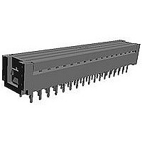
044 ASSY SYS 50 PADDLEBOARD

1-5111595-0

Manufacturer Part Number
1-5111595-0
Description
044 ASSY SYS 50 PADDLEBOARD
Manufacturer
TE Connectivity
Datasheets

Specifications of 1-5111595-0

Type Of Connector
Paddleboard
Connector Type
Connector Assembly
Mating Connector Lock
Without
Wire/cable Type
Ribbon Cable
Mount Angle
Vertical
Pcb Mount Retention
Without
Cover Material
Polyester
Voltage (vac)
30
Insulation Resistance (m?)
5,000
Contact - Rated Current (a)
0.5
Termination Post Length (mm [in])
2.54 [0.100]
Number Of Positions
44
Ribbon Cable Centerline Spacing (mm [in])
0.64 [0.025]
Contact Termination Type
Through Hole
Contact Base Material
Copper Alloy
Contact Plating, Mating Area, Material
Tin-Lead
Housing Material
Liquid Crystal Polymer (LCP)
Ul Flammability Rating
UL 94V-0
Housing Color
Black
Rohs/elv Compliance
RoHS compliant, ELV compliant
Lead Free Solder Processes
Wave solder capable to 240°C, Wave solder capable to 260°C, Wave solder capable to 265°C
Rohs/elv Compliance History
Always was RoHS compliant
Applies To
Printed Circuit Board
Temperature Range (°c)
-65 – +105
.
1.1.
1.2.
1.3.
2.
2.1.
2.2.
3.
3.1.
©2011 Tyco Electronics Corporation,
a TE Connectivity Ltd. Company
All Rights Reserved
TE logo is a trademark.
SCOPE
Content
This specification covers performance, tests and quality requirements for AMPLATCH* System 50,
.025 inch centerline, flat cable round conductor connector receptacle and paddleboard. Although not
specifically tested, paddleboard is considered qualified to this specification due to its identical
termination slot design including slot width, length, material thickness, and all other dimensions in the
wire termination area. These connectors are defined as follows: receptacle contacts crimped to .025
inch centerline ribbon cable having 30 AWG solid, 30 AWG stranded, or 32 AWG stranded conductors.
Complete receptacle assemblies mate to .015 inch square or round posts on an .050 X .100 inch grid
pattern with equivalent post length of .125+ .010 inch. Complete paddleboard assemblies are soldered
directly to a printed circuit board.
Qualification
When tests are performed on the subject product line, procedures specified in Figure 1 shall be used.
All inspections shall be performed using the applicable inspection plan and product drawing.
Qualification Test Results
Successful qualification testing on the subject product line was completed on 30Oct01. The
Qualification Test Report number for this testing is 501-189. This documentation is on file at and
available from Engineering Practices and Standards (EPS).
APPLICABLE DOCUMENTS
The following documents form a part of this specification to the extent specified herein. Unless
otherwise specified, the latest edition of the document applies. In the event of conflict between the
requirements of this specification and the product drawing, the product drawing shall take precedence.
In the event of conflict between the requirements of this specification and the referenced documents,
this specification shall take precedence.
TE Connectivity (TE) Documents
!
!
!
!
Commercial Standard
EIA-364: Electrical Connector/Socket Test Procedures Including Environmental Classifications
REQUIREMENTS
Design and Construction
Product shall be of the design, construction and physical dimensions specified on the applicable product
drawing.
109-197: TE Test Specifications vs EIA and IEC Test Methods
114-25029: Application Specification
114-25040: Application Specification
501-189: Qualification Test Report
| Indicates change
*Trademark
Product
Specification
AMPLATCH* System 50 Connector Receptacle and Paddleboard
For latest revision, visit our website at www.te.com/documents.
For Regional Customer Service, visit our website at www.te.com
Other products, logos, and company names might be trademarks of their respective owners.
108-1109
11Mar11 Rev B
1 of 6
LOC B

Related parts for 1-5111595-0

1-5111595-0 Summary of contents

Page 1

... These connectors are defined as follows: receptacle contacts crimped to .025 inch centerline ribbon cable having 30 AWG solid, 30 AWG stranded AWG stranded conductors. Complete receptacle assemblies mate to .015 inch square or round posts on an .050 X .100 inch grid pattern with equivalent post length of .125+ .010 inch. Complete paddleboard assemblies are soldered directly to a printed circuit board ...

Page 2

... Temperature: -65 to 105° C 3.4. Performance and Test Description Product is designed to meet the electrical, mechanical and environmental performance requirements specified in Figure 1. Unless otherwise specified, all tests shall be performed at ambient environmental conditions per EIA-364. 3.5. Test Requirements and Procedures Summary Test Description Initial examination of product ...

Page 3

... Measure force necessary to mate specimens at a maximum rate of 12.7 mm [.5 in] per minute. Measure force necessary to unmate specimens at a maximum rate of 12.7 mm [.5 in] per minute. EIA-364-32, Test Condition II. Subject unmated specimens to 5 cycles between -65 and 105° C. EIA-364-31, Method III ...

Page 4

... Mixed flowing gas Final examination of product (a) See paragraph 4.1.A. NOTE (b) Test group is unmated and unterminated. (c) Numbers indicate sequence in which tests are performed. (d) Precondition specimens with 10 durability cycles. 4. QUALITY ASSURANCE PROVISIONS 4.1. Qualification Testing A. Specimen Selection Specimens shall be prepared in accordance with applicable Instruction Sheets and shall be selected at random from current production ...

Page 5

... Acceptance Acceptance is based on verification that the product meets the requirements of Figure 1. Failures attributed to equipment, test setup or operator deficiencies shall not disqualify the product. If product failure occurs, corrective action shall be taken and specimens resubmitted for qualification. Testing to confirm corrective action is required before resubmittal. ...

Page 6

... No straight posted header is required with Paddleboard which solders directly to the NOTE printed circuit board. Vibration & Mechanical Shock Mounting Fixture Rev B Figure 4 108-1109 ...

Related keywords